

Maintaining safety of overhead catenary on the Shinkansen
Posted: 6 February 2015 | | 1 comment
There are many kinds of overhead catenary systems and they all interact with pantographs. In Japan, efficiently maintaining the stress of catenary systems is considered as the most important factor for railway safety. Takamasa Hayasaka and Masatoshi Shimizu from the Railway Technical Research Institute (RTRI) believe the European rail sector can learn a lot from Japanese overhead catenary and pantograph experience…
There are many kinds of overhead catenary systems and they all interact with pantographs. In Japan, efficiently maintaining the stress of catenary systems is considered as the most important factor for railway safety. Takamasa Hayasaka and Masatoshi Shimizu from the Railway Technical Research Institute (RTRI) believe the European rail sector can learn a lot from Japanese overhead catenary and pantograph experience.
It has been 50 years since the start of Shinkansen high-speed rail operations in Japan. Although the maximum speed was originally 210km/h, it has gradually increased over time and now stands at 320km/h, with speeds expected to increase further still in the future.
When operations began in 1964, the Shinkansen originally used a BT power-feeding system with 6-8 pantographs for each trainset. When a BT power-feeding system is used for heavy loads like the Shinkansen, certain sections within the system are prone to large discharges. In addition, pantograph resonances, contact losses, sound noise and electrical noise can be generated due the use of many pantographs.
After the inauguration of the Shinkansen, the Japanese national railways company (which is now privatised) developed some techniques to solve the aforementioned problems and the BT power-feeding system was changed to an AT power-feeding system. Since the changeover sections were adopted at the time of inauguration, we could use the bus cable to reduce contact losses by decreasing the number of pantographs. The improvements implemented have contributed to the efficient performance and the overall safe-keeping of the overhead contact system. However, one element which has not been changed since the inauguration is the pantograph-uplift-force.
Since its inauguration, the Shinkansen has used a 54N uplift-force for the pantographs to prevent large uplifts of the contact wire which can be caused due to many pantographs being used. The lower uplift-force was considered to be effective in that it could prevent contact wire breaks due to the metal fatigue. However, in 1974 and 1975, approximately 10 years after inauguration, two accidents occurred involving a contact wire break at the crossovers sections. This resulted in the adoption of a study to assess the metal fatigue of contact wires.
There are some differences between Japanese high-speed train systems and those found across Europe. We consider our unique experience of contact wire breaks, feeding systems and the current collecting system to be effective for high-speed trains. Our systems can reduce metal fatigue and improve the performance and safety of overhead catenary systems.
Contact wire breaks
Occasion of event
The aforementioned accidents in 1974 and 1975 triggered the need for a study into the metal fatigue of contact wires. Figure 1 shows an example of a broken cross-section due to the metal fatigue of the contact wire; the enlarged section shows the appearance of the beach mark which proves that the reason for the break was due to metal fatigue. After those accidents, the way we view and assess metal fatigue of contact wires was stepped-up in Japan.
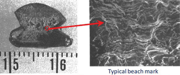
Figure 1: Broken cross-section example on contact wire
Viewing metal fatigue of contact wires in Japan
Calculation of contact wire vibrations
During the first phase of the Shinkansen, the number of pantographs to pass through a section was set at approximately three million before there was the need to replace the contact wire due to wear. The number of vibrations was set at 10 million in consideration of the vibrations by winds and the residual vibrations after the pantographs had passed through.
Metal fatigue of the contact wire
The diameter of a Cu contact wire whose cross-section is 110mm2, which is popular in Japan, is 12.3mm and the contact wire is usually replaced when the diameter reaches 7.5mm. The break stress by tension of the contact wire is 350MPa and is shown at point ‘A’ in Figure 2. The repeat allowable stress in the direction of up and down against contact wire length is 120MPa in the case of no tension (at point ‘B’ in Figure 2). The repeat allowable stress at 7.5mm in diameter is decreased to 70MPa under 9.8kN tension strength (at point ‘C’ in Figure 2). In addition to this, it should be considered that the repeat allowable stress of the contact wire would be affected by the simultaneous application of bending and rotating stress as well as heat. This is the reason why the Japanese national railways set the stress (strain) limitation for the prevention of contact wire breaks at 60MPa (500μst.)1.
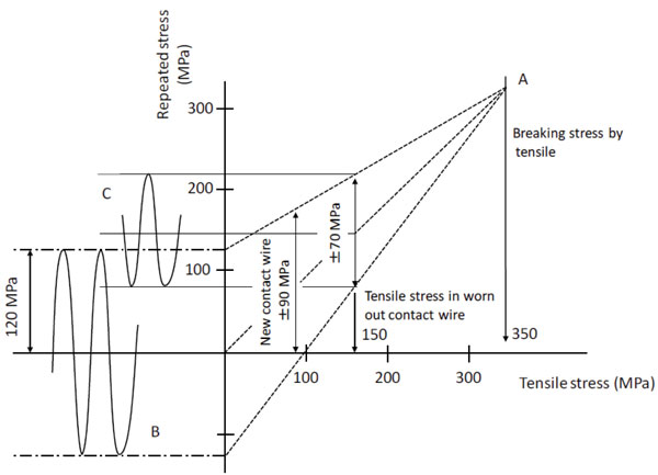
Figure 2: Reduction of allowable stress for contact wire
Power-feeding system and current collecting system
Change from BT system to the AT system
As already mentioned, upon inauguration, the power-feeding system for the Shinkansen was the BT system which returned the current on the return wire to substations via booster transformers. However, after the inauguration, large arc discharges were generated at the sections due to the heavy load of the Shinkansen.
So, Japan changed the BT power-feeding system to an AT power-feeding system to prevent a large arc occurring at the BT sections.
Also to mention, 1972 saw the inauguration of the Sanyo-Shinkansen line. The AT power-feeding system was adopted for this line, even before the changeover of the initial line in 1983.
In addition to the aforementioned aspects, since the changeover sections were adopted at different sections at the time of inauguration, we could use the bus cable to reduce contact losses by decreasing the number of pantographs.
Changeover section
One of the unique systems of the Shinkansen is the changeover section. Usually, when a high-speed train goes through a different phase section in front of a substation or a sectioning post, the train would lower the pantographs or keep the notch-off before the section. But the Shinkansen can go through it with the notch-on since it uses the changeover section.
Figure 3 schematically shows the work of a changeover section. The way the changeover section works according to the movement of a Shinkansen train is as follows:
- A Shinkansen train approaches a changeover section
- The Shinkansen enters the changeover section and the SS1 side switch opens
- Then, the SS2 side switch closes
- The Shinkansen train passes through the section
- After the Shinkansen train passing, the SS2 side-switch opens
- Finally, the SS1 side switch closes and the changeover section returns to its original condition.
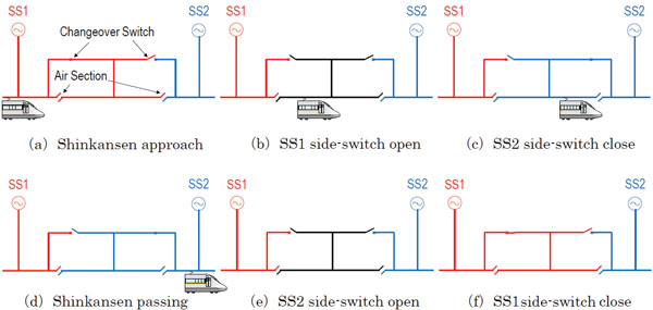
Figure 3: Work of changeover section with Shinkansen moving
Adoption of a bus cable and reduction of the number of pantographs
Figure 4 schematically shows two trainsets – one at the time of inauguration and the other at present. When the Shinkansen was inaugurated, it used eight pantographs per trainset. However, after upgrading to the AT power-feeding system, the changeover sections were adopted and the number of pantographs was reduced, alongside the adoption of a bus cable. The uplift-force of the Shinkansen pantograph has been kept at 54N, however, by using the bus cable in a trainset. Owing to the bus cable, the train can keep in contact with the contact wire, with the result that the contact loss ratio is reduced because the pantographs make up for each other in case a fault occurs. Moreover, the improvements can reduce the electrical noise and the sound noise from the pantographs.
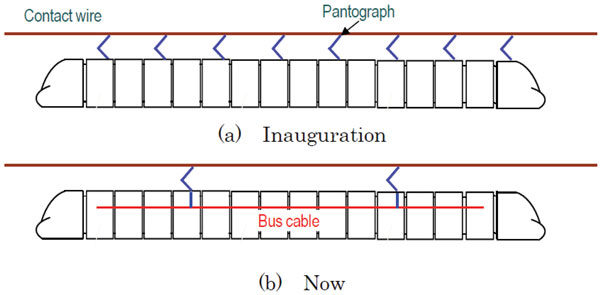
Figure 4: Change of the number of pantographs
Managing the installation of the overhead catenary system2
The contact wire should be installed at the correct height without errors because the errors influence the current collecting performance. However, the actual installation height in the fields has errors. Conventionally, an index for estimating the errors of the installation is the gradient of the contact wires, but it is not enough to estimate the current collecting performance on high-speed lines only by this index. This is why we have proposed new guidelines for the management of overhead contact system installation to keep the proper current collecting performance in where the train speed is more than 300km/h. The proposed procedure for the management of the overhead contact system installation is as follows.
First, the gradient and the curvature of the contact wire in the field, which are indices for the installation errors, are collected and the real data of the installation height are measured in fields and the current collecting performance is evaluated by simulation based on the real data. Next, the simulation result is statistically analysed to abstract the evaluation indexes that strongly relates to the installation errors. After that, the evaluation index is adjusted in simulation to improve the current collecting performance. Figure 5 shows the estimation index of the installation errors for an operation speed of 352km/h. Also, through the procedure similar to the above, another valuation index can be prepared for higher operational speed.
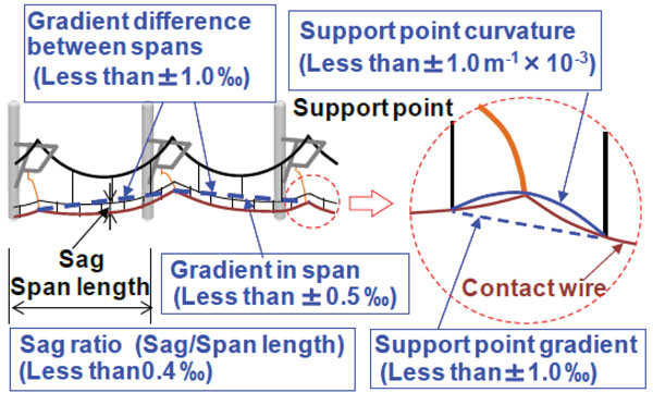
Figure 5: Evaluation index for installation errors and desired values
References
- RTRI, ‘Overhead Contact System and Pantograph’ pp.6.29-6.30, 2010 (in Japanese)
- Mitsuo ABOSHI and Mizuki TSUNEMOTO ‘Installation Guidelines for Shinkansen High Speed Overhead Contact Lines’, QR, RTRT, Vol.52, No.4, 2011
About the authors
 Takamasa Hayasaka is a Senior Researcher within the Contact Line Structures Lab at the Railway Technical Research Institute (RTRI). Takamasa joined the RTRI in 2001 and is engaged in the studies of catenary structures and arc phenomena between pantographs and contact wires.
 Masatoshi Shimizu is Head of the Contact Line Structures Lab at the Railway Technical Research Institute (RTRI). Masatoshi joined the RTRI in 1987 and is engaged in the studies of current collecting performances and measures of poles against earthquakes.


Compliments,I study in HS lineas in Italy up to 400Km/h…with a Elastic hanger call “PENDIFLEX”….the interaction between CW and pantho is optimized.PZ