Implementation of the ÖBB Maintenance Plan according to international standards
Posted: 26 March 2009 | | No comments yet
Overview of the Technical Specification for Interoperability (TSI) relating to the infrastructure subsystem of the trans-European high-speed rail system.
Overview of the Technical Specification for Interoperability (TSI) relating to the infrastructure subsystem of the trans-European high-speed rail system.
The Technical Specification for Interoperability (TSI) relating to the infrastructure subsystem of the trans-European high-speed rail system, requires that every infrastructure manager draws up a Maintenance Plan. This must set out the necessary inspections, the frequency, the qualification of staff, the measuring methods and the necessary action to be taken. At Austrian Federal Railways (ÖBB) the Maintenance Plan went into force in 2007.
The data measured by the permanent way measuring cars are of great significance for this. Before the Maintenance Plan went into force, the number of limit value exceedances to be expected was forecast on the basis of track geometry data existing across the network. Parallel with the drafting of prEN13848-5, three limit values dependent upon speed were laid down for each of seven track geometry parameters.
The limit value exceedances are identified whilst the measuring run is being performed and, if necessary, safety measures are taken immediately. After the measuring run, it is possible for every member of the service staff to retrieve detailed information about every individual fault as well as statistics via a specially developed, user-friendly Intranet tool at any time.
For the correction of spot faults, special tamping machines are available in addition to the maintenance tamping programme.
One of these special machines is operated by ÖBB Betrieb AG all year round for this purpose.
Environment of International Standards
The Infrastructure TSI1 requires that a Maintenance Plan be drawn up. According to the TSI, the responsibility for drawing up the Maintenance Plan lies with the infrastructure operator. The Maintenance Plan must lay down the required inspections and their frequency, the qualification of the staff and the methods of measuring. Moreover, safety-relevant limit values must be given for various parameters and the necessary action to be taken must be defined. The TSI requires immediate action limit values for the following parameters:
- Track gauge
- Longitudinal level
- Crosslevel
- Alignment
- Twist
- Inspection dimensions of turnouts
The Maintenance Plan is thus the new inspection regulation on Austrian Federal Railways conforming to the TSI.
The first infrastructure TSI was drawn up in 2003 and concentrated on high-speed traffic (high-speed TSI). It does, however, also apply to conventional lines under 160km/h which are scheduled for upgrading or which are feeder lines to the high-speed lines. In Austria, lines longer than 2,500km come under the application of the high-speed TSI.
A revision of this standard (HS-TSI rev.) and a draft for the respective TSI for conventional routes (CR-TSI) has almost been completed and will shortly go into force.
A working group of the CEN TC256 WG28 has been commissioned to draw up the European Standard EN138482 which should provide technical support for the TSI. The EN consists of several sections. Section 1 defines the parameters of a track geometry measurement and is already in force.
A new feature for most railway administrations is that for alignment and longitudinal level, in the future no versine measurement of any kind shall be used, but true to shape space curves with a transfer function which remains 1 consistently in the wavelength range between 3 and 25.
Part 2 of the European Standard defines the specification for measurement systems to ensure that all track recording vehicles produce comparable results when measuring the same track and defines repeatability and reproducibility for the measurement of all track geometry parameters. The introduction of EN13848 Part 1 and 2 has now laid the foundation for comparable track geometry measurements across Europe. Until now this comparability was not available in wide areas.
Part 1 and 2 of the EN13848 were compiled in a very consensual manner but Part 5, which governs the intervention limits of the track geometry parameters, was more controversial and caused some discussion. In Part 5, an immediate action limit is laid down as normative for each parameter and there is also an intervention limit and an alert limit informatively. After a discussion process lasting many years, the final draft was passed by a ‘Comment Resolution Meeting’ in June 2007 without objections and went into force in March 2008. Therefore, the ÖBB Maintenance Plan was in compliance with this European standard one year before it went into force.
Contents of the ÖBB Maintenance Plan
The greatest difference between the former inspection regulations and the new ÖBB Maintenance Plan is the changeover from limit values to intervention limits. The limit values of the earlier inspection regulations were given throughout for manual measurements in an unloaded state. The manual measurements regularly required over the entire area of all tracks did not meet the latest technical standards. Moreover only one limit value was given for each parameter. Up to this limit value the track network was fully operational, in the event of a minimal exceedance of this value, the state of the network was in the red zone.
In the new Maintenance Plan three intervention limits are given for each parameter:
- The alert limit
- The intervention limit
- The immediate action limit
Therefore, during the regular inspections, measuring systems record not only the occurrence of the fault, but also observe the development of the fault over time. Depending upon the size of the fault, the action taken to remedy them has to be placed in respective order of urgency. All values given in the new ÖBB Maintenance Plan are measured values in the loaded state and are therefore measured by the permanent way measuring coach across the entire network.
Determining the intervention limits
For determining the intervention limits, the data measured by the permanent way measuring cars have a great significance. Before the Maintenance Plan went into force, a forecast was made of the number of limit value exceedances to be expected on the basis of track geometry data existing across the network. This was performed through extensive statistical analyses of existing, standardised track geometry data which were available across the network from an enormous database system on the basis of raw data, i.e. every 25cm.
These include:
- Track gauge (peak value + 100m mean)
- Longitudinal level (space curve 3-25m)
- Crosslevel
- Alignment (space curve 3-25m)
- Twist (3m, 9m, 16m base)
- Twist relative
In line with the draft of prEN13848-5, three limit values dependent upon speed were laid down for each of these parameters: an immediate action limit, an intervention limit and an alert limit.
To estimate the number of limit value exceedances to be expected on the ÖBB network before it went into force, speed-dependent cumulative frequency distributions were calculated for each of these track geometry parameters across the network.
Taking the parameter ‘alignment’ as an example (see Figure 4) shows that the immediate action limits in the ÖBB Maintenance Plan are stricter than in the EN 13848-5, but these are still higher than the quality standard QN3 which plays an important role in the vehicle approval process as per EN 14363.
Support of the correction process
With the introduction of the Maintenance Plan, a new workflow was laid down which is supported by new IT applications.
On board the permanent way measuring coach, the measured values are tested on all limit values immediately after measuring. To do this, it was absolutely necessary to have the exact information about the local maximum permissible speed in digital form in the computer systems on the permanent way measuring coach. In this way, it is possible to print out all values exceeding the immediate action limits and intervention limits straight away on the printer in the recording coach. This print-out is a new and important document for the local district inspector responsible for the inspection of faults and for taking urgent action in order to guarantee the safety.
After the measuring run, all measured values are filed in a central database as raw data (i.e. one measured value per 25cm). Using an Intranet application it is possible for each member of the service staff to retrieve detailed information to each single fault as well as statistics in a very user-friendly way. This web application is also used to enter comments by the responsible district inspector and these form the basis for detailed planning of the fault correction measures. Besides giving the exact kilometre location of the fault, information about the surroundings, such as the proximity of railway crossings or bridge connections, and the exact positioning of the locality in GPS coordinates is also offered optionally.
In the future, it is also planned to link such coordinates to a geographic information system (GIS) enabling these to be registered in GPS-coded orthophotos. These orthophotos are currently being procured by ÖBB Real Estate and compiled in a GIS of this kind.
Correction of spot faults
Faults can be corrected using a variety of methods, primarily by distinguishing between geometric faults and gauge faults. Specialist spot fault elimination machines are used for the correction of geometric faults. During the next measuring run, the permanent way measuring coach can measure and record the development and/or correction of the fault.
Thus, spot fault tamping is an additional method of correction in addition to the scheduled tamping passes. These scheduled maintenance tamping operations will continue to be carried out on more than 1,000km annually following the basic principles of the ‘Strategy Permanent Way’ project3.
Due to the operation of specialist spot fault elimination machines, it has been possible to lower the correction time for geometry faults and clearly raise the quality of spot fault tamping.
The Maintenance Plan specified in the TSI went into force on Austrian Federal Railways in spring 2007.
Summary
The TSI relating to the trans-European high-speed rail system requires that a maintenance plan be drawn up which sets out the necessary inspections, their frequency, the qualification of the staff, the measuring methods and the action to be taken. Austrian Federal Railways’ maintenance plan went into force in 2007.
In accordance with EN13848-5 three limit values were laid down for each of 7 track geometry parameters. The number of exceedances was estimated on the basis of existing measured data of track geometry worldwide. Limit value exceedances are identified immediately during the measuring run, and these can be retrieved easily by any member of the service staff after the measuring run using a specially developed Intranet tool. For the correction of spot faults, special tamping machines are available in addition to the maintenance tamping programme.
References
- European Commission decision 2002/732/EG of 30.5.2002 concerning the technical specification for interoperability relating to the infrastructure subsystem of the trans-European high-speed rail system referred to in Article 6(1) of Council Directive 96/48/EG
- EN13848-1:2003, EN13848-2:2003, prEN13848-3: 2007, prEN13848-5:2007, all compiled by CEN/TC256 SC1 WG28
- Dr. P. Veit: Strategie Fahrweg [Strategy Permanent Way], postdoctoral thesis Graz University of Technology
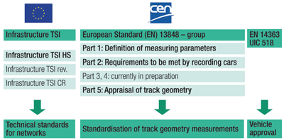

Figure 1: Environment of international standards
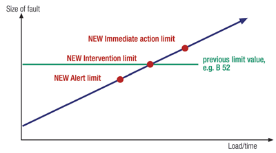

Figure 2: From limit values to intervention limits
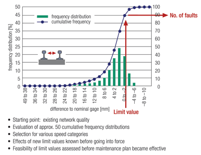

Figure 3: Estimation of the effect of limit values over network-side, speed dependent cumulative frequency distributions
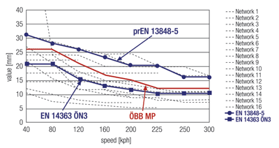

Figure 4: Immediate action limits for the 'alignment' parameter in 16 European networks
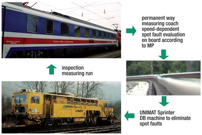

Figure 5: Spot fault tamping
Issue
Related topics
Infrastructure Developments, Interoperability & Liberalisation


