New horizons for train location and signalling
Posted: 11 August 2017 | Alessandre Giuliani, Giuseppe Fazio, Matteo Telesca, Mauro Giaconi, Salvatore Vetruccio | No comments yet
Despite the many great advancements that have taken place in railway signalling systems, some concerns still exist – notably regarding SIL 4 (Safety Integrity Level) train locationing. Giuseppe Fazio, Mauro Giaconi, Salvatore Vetruccio, Matteo Telesca and Alessandro Giuliani from the Italian rail community highlight the main issues related to current systems alongside some proposed solutions that are under consideration by the academic community.
Present situation/issues
Insulated joints
These relate to track circuits that consist of galvanically isolated rail links. In this context, circulating currents in rails are frequently coded in order to communicate with trains semaphore states (Coded Current Automatic Block – BACC). The issues related to the presence of such joints include the following:
- The joints set limits to train speeds
- They represent single points of failure with resulting maintenance issues
- They are intrinsically difficult to check their own integrity and that of the overall rail
- Above all, their replacement with more sophisticated systems involves the issue of non-compatibility with present in-vehicle systems. Sometimes on updating rail links – despite being a huge additional cost – it is preferable to sacrifice compatibility with present in-vehicle systems for signal continuous repetition through coded currents. The priority is to remove fragile insulated joints.
Usually used track circuits without insulated joints are axle counters and audio frequency track circuits. The main issues encountered with such circuits are as follows:
Axle counters track circuits
- Axle counters count the number of input and output axles and so are not able to detect abnormal situations related to jumps in counting
- Axle counters are sensitive to their vertical location along the rail.
Audio frequency
- Since we need to work at high frequency in order to avoid interferences from other engines, and considering the high electrical attenuation of rails, audio frequency track circuits have to work with low power level signals, with minimal differences between free or busy track circuits
- Audio frequency systems are subject to the ‘cross talk’ phenomena that results from neighbouring rails due to high frequency
- Owing to high electrical attenuations, audio frequency track circuits have limitations in length, with an associated requirement to readjust electrical parameters along rails (e.g. phasing capacitors every few dozen metres and tuned filters that make use of stretches of rail in the circuits)
- Audio frequency systems don’t have accurate track circuit delimitation owing to issues related to filters and the need to consider very low value currents.
Virtual circuits
Virtual circuits are related to vehicle tracking systems without any ground parts, generally based on GPS systems or on odometry equipment. These systems are generally avoided due to the difficulty of obtaining a suitable security level (SIL 4).
To date, it is assumed that only SIL 2 prototypes have been made.
Track characterisation
Various simulations are currently underway considering circuits bound by two short circuits and powered by a central electrical generator.
Insulated joints
In the case of BACC circuits the main feature of the proposed solution is the complete elimination of insulated joints, leaving equipment on-board the train – as well as their manner of operation – unchanged. This solution has the following benefits:
- It can operate on ERTMS rail links (not AC electrically operated) in order to indicate occupied tracks and to allow the passage of traditionally equipped trains
- It offers the opportunity of rail integrity testing
- It is very cheap and easy to achieve
- It is inherently immune to wrong codes (third rail problem)
- It is fully compatible with present coded current systems
- It is easy to achieve with SIL4 level
- It allows the coexistence of traditional (with insulated joints) and innovative rail links, by enabling a gradual updating of the systems.
Mode of operation
It is assumed that the arrow in Figure 1 indicates the direction of motion.
Between G1 and G2, after passing point G1, the rail vehicle reads the electromagnetic field generated by the part of the current that is produced by the generator in G2, which flows in its direction (i.e. towards G1).
The other part of the current produced by the generator in G2 ends up in the short circuit in G3.
Between G2 and G3, after G2, a short circuit is created between G2 and A31, so the impressed current doesn’t even get to A31. The switch is then open; local generator (G3) is triggered with the code related to that circuit (G2-G3); and the switch located in the further downstream point (not shown in the figure) is switched off.
The possible addition of further current sensors (for instance, the doubling of those shown in Figure 2), can help identify more precisely and quickly the location of rail vehicles.
With this solution, it is a nuisance to update any rail links without maintaining compatibility with on-board systems [1].
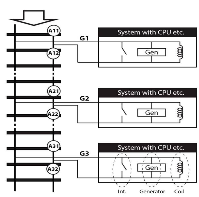
Figure 1: Mode of operation
High performance track circuits ‘CDB HP’
The main features of this innovative proposed solution include the following:
- It is cheap
- It is easily implemented with the appropriate security level (SIL 4)
- It allows the operation of rail links of a greater length than those operated by audio frequency track circuits
- It eliminates the need of electrical interventions carried out in all rail links (such as phasing capacitors every few dozen metres, and the tuning of filters, which make use of stretches of rail in the circuits)
- It is exempt from the axle counters issues afore-referenced
- It is immune to noise due to DC or AC electrical traction
- It allows, as auxiliary performance, rail integrity control
- It permits – albeit with changes on board the train (not entirely compatibly with present BACC) – continuous signal repetition to be carried out on train cabs without the need for radio systems.
The set consists of a transmitter and receiver and uses many simultaneous transmission frequencies chosen in such a way that – non-being, mutually multiple, or sub multiple – any possible noise on certain frequencies cannot have simultaneous harmonic components on more than one transmission frequency. Such frequencies are chosen on the basis of typical noise due to electrical traction and are lower than all those which have issues for transmission due to high rail electrical attenuation (typically 300Hz).
The possibility that sensors receive at least three or four frequencies with the right associated codes when a train convoy is interposed between transmitter and receiver, is well below 10-9. However, the probability that electrical traction noise blinds at the same time at almost every frequency is unlikely to prevent system availability [2].
Virtual circuits
In order to obtain an appropriate security level regarding longitudinal position and integrity of train convoy, a system is currently under study which consists of two GPS sensors – one ahead of the train and the other at the rear of the train. In this case, if the two tracked positions are congruent with vehicle length, with any winding rails, with previous positions and with system speed, the error location probability is well below 10-9 (SIL 4).
The probability that any error on satellite signals maintains the congruence of the two GPS Surveys with aforementioned would appear to be irrelevant. However, this probability can be set at zero by using several satellite constellations [3-5].
An increase in inaccuracy can occur due to variable propagation conditions but can be reduced by using test points located on rails [6,7].
With regard to the resolution necessary to safely distinguish adjacent rails, rather than using sophisticated satellite systems, it is good to use iron or concrete bars applied to railroad ties, as they are readable on board the train with lasers or magnetic sensors.
As shown in Figure 2, the railroad ties can have two bars in fixed locations related to four different codes.
It is a simple process to code the various railroad ties with a different number of bits. Moreover, the sequence of coded railroad ties allows to code with absolute certainty both various rail links and actual location, which is useful information for any recalibration of GPS systems [3,7,8].
In fact, any error on coded sequences associated with railroad ties during installation does not cause problems. It is sufficient that such a situation is highlighted in a database upon testing.
To install this system on service rails entails merely running over them with a nail gun bogie, since there are no ground electronics. Rail controls should be made by on board equipment.
For this purpose, three types of sensors are planned, whose output are recorded with proper space-time reference points.
The first type is based on two video cameras; one ahead of the train and the second at the rear of the train.
The second type is based on accelerometers, which record vertical and cross wheel motions in order to verify whether such motions are consistent with necessary tolerances, and considering different speeds and different meteorological situations, with previous passages of other trains [9].
With regard to the third type, in order to make use of electrical currents, it is necessary to inject suitable currents into rails – at both the front and rear of the train – and to verify current partition due to the presence of train axles on the one hand and to rail electrical parameters on the other side. A generator injects current into rail through a transformer whose primary winding is a coil with N loops integral to the train. Furthermore, the magnetic flux is linked to secondary winding, which consists of two axles of the bogie; the four wheels of the bogie; and the two parts of the rails between the front wheels and rear wheels of the bogie[3]. This system can also be used to confirm that the train is unbroken.
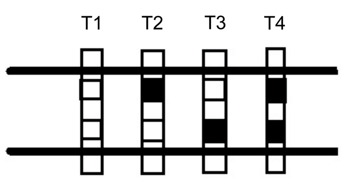
Figure 2: Railroad ties can have two bars in fixed locations related to four different codes
References
- Fazio, G., Sacerdoti, D. ‘Coded current automatic block system without the use of insulated joints compatible with present train on board subsystem’ PCT/IT2014/000319
- Fazio, G., Sacerdoti, D. ‘Low attenuation and high performance track circuit’ PCT/IT2015/000188
- Fazio, G., Sacerdoti, D. ‘Metodo e relativo attrezzaggio per la localizzazione di rotabili ferroviari con livello di sicurezza appropriato tramite localizzazione satellitare’ Patent application n. 102017000029446 del 16 March 2017
- A New GNSS Single-Epoch Ambiguity Resolution Method Based on Triple-Frequency Signals, Shengli Wang, Jian Deng, Xiushan Lu, Ziyuan Song and Ying Xu, ISPRS International Journal of Geo-Information, 18/2/2017
- The Global Positioning System, Jules G. McNeff, IEEE Transactions On Microwave Theory And Techniques, Vol. 50, No. 3, March 2002 645
- Bar-Sever, Y., Young, L., Stocklin, F., Heffernan, P., Rush, J. The Global Differential GPS System (GDGPS) and The TDRSS Augmentation Service for Satellites (TASS), Jet Propulsion Laboratory, California Institute of Technology, ESA 2nd Workshop on navigation equipment, Noordwijk, The Netherlands, December 2004
- Fazio, G., Quatrini, D. ed altri ‘Satellite positioning systems: assessing state-of-the-art technology for railways’ European Railway Review, Issue 3 2011 pp.47-49
- Fazio, G., Quatrini, D., Giaconi, M. ‘Improved location of trains involved in safety critical scenarios’ European Railway Review, Issue 1 2012 pp.26-28
- Fazio, G., Sacerdoti, D. ed altri ‘Acoustic Signal Processing to Diagnose Transiting Electric Trains’ IEEE Transaction on Intelligent Transportation Systems vol. 6 June 2005 pp. 238–243.
Biography
Salvatore Vetruccio holds a Ph.D in Electronics Engineering and has worked for Italcertifer S.p.a (Gruppo Ferrovie dello Stato Italiane) since 2011. Having joined the assessor team in ‘Control- Command-Signalling’ he has spent recent years developing automated test benches and electronic mobile instrumentation for assessing subsystems in railway signalling. He also carries out research with the University of Rome Tor Vergata regarding simulators and models in radiation physics.
Matteo Telesca is a B.o.E and a M.o.E. student graduating in electronics engineering, developing an experimental thesis for pioneering applications in railway.
Mauro Giaconi has extensive technical and engineering experience having both worked in the industry and lectured at various academic institutions throughout his career. He has taught postgraduate courses on cable, radio and satellite telecoms since 1972, and has co-authored numerous books, journal papers and conference papers.
Giuseppe Fazio has been Professor of Electrical Measurements at the Department of Electronics at the University of Rome ‘Tor Vergata’ since 1987. Between 2009 and 2011 he was a member of the TAB project INESS of the Seventh European Framework Programme, evaluating the signalling techniques used by different EU states. He is also holder of various publications and patents in the railway sector.
Alessandre Giuliani is a B.o.E and a M.o.E. student graduating in Electronics Engineering, developing an experimental thesis for pioneering applications in railway.