The Wheel/Rail-Interface Study
Posted: 15 September 2015 | Jani Dede, Marc Reimann, Uwe Reimann | No comments yet
Rail operators and infrastructure owners are aware that maintenance of wheels and rails are big cost drivers. For European Railway Review, Jani Dede, Uwe Reimann and Marc Reimann from Bombardier Transportation GmbH, explain a process that has been investigated which studies the wheel/rail-interface in detail to develop an optimised wheel/rail-combination that can be adapted to a railway network. The examination is called the ‘Wheel/Rail-Interface Study’ (WRIS).
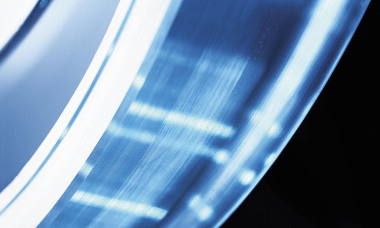
Credit: Bombardier
For as long as the railway has existed, engineers have been involved in creating wheel and rail profiles and researched their combinations. Over time, most of the rail profiles have become standardised1,2, whereas the wheel profiles have become less so3. The shape of a wheel profile is normally defined by either the operator, the vehicle manufacturer, institutions like universities, external contractors, or by history. Once a wheel/rail-combination is established on a network, it will often remain untouched.
When problems occur, such as increased wear on wheels and rails or noise emissions that disturb residents, the first step is often to eliminate the symptoms rather than to treat the source of the problem. The typical response is to remove these symptoms by installing stationary and/or mobile friction modification systems instead of establishing the root cause of the problem by analysing the wheel/rail-interface.
Operators often have worries that a change to the wheel/rail-combination on their network will cause a chain of changes in the whole system that they cannot foresee. If the operator does not have the knowledge in this field, often the message is simple: ‘never change a running system’.
These concerns can’t be denied. Changing the wheel/rail-combination can have a huge impact on the running behaviour and the stability of the vehicle, can change the wear of wheels and rails, can cause noise emissions, can change overhaul intervals, can increase costs and even jeopardise the homologation when the calculation of safety against derailment changes. In summary, a change to the wheel/rail-combination can cause the complete system to deteriorate; however, with the appropriate changes it is also possible to improve it considerably.
There is large potential for improvement to current networks and the operators have started to open up their minds to this topic, not least because they know that maintenance of wheels and rails are big cost drivers.
Against this background, the dynamics department of Bombardier Transportation GmbH (BT) in Siegen (Germany) has created a process that studies the wheel/rail-interface in detail to develop an optimised wheel/rail-combination adapted to the customer’s network. This examination is called the ‘Wheel/Rail-Interface Study’ (WRIS). Additional figures related to the WRIS can be found in reference point 4 of this article.
Steps of the WRIS
Background
Wear emerges from relative speeds between two surfaces, called slippage. When the slippage within the wheel/rail-contact is small, the material removal on the wheel and the rail is also small. Wear will be minimised if the wheels of a railway vehicle can roll without resistance on the rails.
When driving through a curve there is the known conflict of different running distances of the inner and outer wheel. For independent (single) wheels this is not a problem as they can roll free without longitudinal slippage. However, wheelsets have the axle as the coupling element between the left and right wheel.
To make a free rolling wheelset possible without any longitudinal slippage, both wheels need to run with different rolling radii in a curve. The outer wheel rolling radius has to be bigger than the inner one. This difference is called the rolling radii difference Δr.
While the vehicle is in motion, the leading wheelset is normally pushed to the outside of the curve due to the acting centrifugal force. The wheel flange of the outer wheel therefore comes closer to the rail, whereas the inner wheel flange diverges from the rail. This movement can be used to develop a wheel profile that can provide the required rolling radii difference for a resistance-free rolling of the wheelset.
As track networks naturally include many different curve radii, what is the maximum rolling radii difference that should be chosen? This value is only optimal for one specific curve radius – meaning excessive Δr for wider curves and insufficient Δr for narrower curves – therefore it is necessary to determine the maximum rolling radii difference that is best with regard to wear for the whole network. In order to achieve this, the curve radii distribution on the customer’s track network has to be analysed.
Analysis of the customer’s track network
To create a curve radii distribution, the customer has to provide details of their network. The minimum requirements are the curve radii, along with their lengths, and the lengths of the straight track sections. Additionally, information about the transition curves and their lengths should be provided.
With this data the curve radii can be classified in bands, i.e. each curve is assigned to a specific class. With regard to wear, the behaviour of a 48m-curve is comparable to a 52m-curve; therefore both are assigned to the 50m-curve class. The width of the classes can be adapted depending on the track network. This process, using the curve lengths and radii, and the length of the complete network, determines a curve distribution for the network.
Analytical calculation of the optimal rolling radii difference
The following step is to determine the optimal rolling radii by using a complex analytical calculation. Besides the curve distribution, other vehicle and track parameters are used as input parameters for this evaluation. For example, the longitudinal primary stiffness, different loading and weather (friction) conditions and the gauge width are taken into account.
With this data and depending on the maximum achievable rolling radii difference, the wear is predicted iteratively. This calculation is repeated for a range of different maximum achievable rolling radii differences. Figure 1 is an example of the result of this analysis. The graph shows how the wear varies with the rolling radii difference. In this example, the optimum profile has a maximum rolling radius difference of about 6mm.
Development of a wheel profile
After calculating the optimal rolling radii difference for the customer’s track network with respect to wear, it is possible to develop the wheel profile to achieve a wheel/rail-profile combination that guarantees the optimal rolling radii difference. This process is always to develop a wheel profile for a given rail profile.
The rail profiles of the customer’s track network have to be analysed. In all relevant curve radii classes, rail profiles are measured and thus the wear state is determined. Afterwards, in cooperation with the customer, a rail profile has to be chosen for which the wheel profile should be developed. Depending on the condition of the rails it has to be decided if the wheel profile should be generated with respect to a new rail, a defined worn rail or intermediate condition. If vehicles are restricted to only run on certain lines, it is also possible to generate different optimal wheel profiles for different lines.
During the wheel profile development, different criteria are taken into account. The basic requirement is a single-point-contact between rail and wheel over the whole lateral displacement of the wheel. In all conditions, a two-point-contact has to be avoided. This will prevent the high wear caused by slippage of the flange. The contact-point-distribution has to be homogenously spread over the complete tread to avoid hollow wear.
The specific pressure in the contact point should be consistent across the wheel profile. It should not be too high and should not have any high peaks to avoid rolling contact fatigue (RCF) which leads to cracks and resulting in the chipping-off of material of the wheels and rails.
The contact-patch, especially in the area of the root flange, must not be too big. A large contact patch in this area results in high spin creepage, causing high wear.
The conicity of the wheel/rail-profile combinations has to be checked in relation to the running stability of the vehicle. The conicity of a new wheel/rail-profile combination should be in the range of the existing one.
With the above assessment criteria and by means of a tool developed by BT, a set of wheel profiles will be generated for a given rail profile. These wheel profiles satisfy each the aforementioned requirements to differing extents.
The number of generated wheel profiles generated by the process can be extended. This results in a variety of different wheel profiles, each having different characteristics regarding rolling radii difference, conicity, specific pressure and contact-point-distribution.
Now, from all generated wheel profiles, the best wheel profile can be chosen based upon the previously mentioned requirements. With this chosen wheel profile, the new wheel/rail-profile combination can be analysed with respect to the actual wear behaviour.
Validation of the wear model
Being able to analyse the wear distribution of a new wheel/rail-combination on a specific track network requires validation of the wear model itself with the current wheel/rail-interface.
The wear model is a multi-body simulation model (MBS-model) of a vehicle in combination with a simulated track and a defined wheel profile. The simulated track is created based upon the curve distribution determined in the track network analysis. The rail profile may vary depending on the curve radii in the simulated track. This allows the measured rail profiles to be integrated into the simulation.
These MBS-models are then used to perform wear calculations in which the contour of wheel and/or rail is updated following each integration step according to the contact situation. The profiles wear during simulation, which leads to different profile contours at different mileages. These contours are then compared to those of real measurements that were recorded with the same mileage. The validation not only analyses the wear itself through measurable parameters like flange thickness or loss of radius, but also looks at the developing profile shape.
The input parameters of the simulation, for example wheel/rail friction, traction force or loading condition, are changed until the simulated wear matches the measured wear at all mileages. In addition, these input parameters can be changed along the length of the simulated track. This allows for the simulation of varying running conditions, such as wet and dry rails. Braking and traction processes can be varied as well.
As soon as the wear model is validated, all parameters relevant for the wear development are fixed. These inputs are used for the wear simulations with the new wheel/rail-combination.
Wear prediction
After validating the wear model it is possible to give an accurate prediction of the estimated wear on wheels and rails and the estimated mileage of the wheels with the new wheel/rail-interface. This process is not only applicable to existing vehicles, but can also be used for new vehicles during the design-development and bid phase where the input is available.
Further analyses can be performed with the validated model. For example, it is possible to define the correct mileage for reprofiling based on different geometrical parameters, such as the flange height and thickness. Additionally, the benefits of flange lubrication and/or tread friction modifiers on a time- and/or position-based approach can be investigated. The aim of this investigation is always to find the right measures for maximising the mileage, increasing the maintenance intervals and therefore reducing the overall costs.
The WRIS in service
During the examination of the vehicles and the track network of a BT customer, high wear was found on the wheels as well as on the rails. After a relatively short time, the rails were heavily worn at the flange face.
A worn rail profile with high flange face wear was compared to a new rail profile. The evaluation of the wheel measurements showed a flange wear rate between 0.3mm and 0.5mm per 1,000km. The analysis of the wheel/rail-combination has determined that two-point contact is the main cause of the high flange and rail wear.
The customer had to replace the rails with new ones on this curvy track section. This allowed BT to propose a new rail profile with another inclination and a slightly larger track gauge. After the evaluation of the track network data, an optimal rolling radii difference of 7mm was calculated. An analysis was then conducted from the automatically generated wheel profiles.
The rate of increase of the rolling radii difference over the lateral displacement for the selected wheel/rail-combination is relatively high; hence the conicity is higher than with the old wheel profile. The conicity has, in this case, only a minor relevance because the vehicle is only running up to 70km/h and exhibits good damping behaviour; therefore there is very low risk of stability problems. The old wheel/rail-combination develops nearly no rolling radii difference and therefore no conicity.
The optimised wheel/rail-combination can develop a rolling radii difference greater than 7mm. However, this area will not be reached because the contact angle there is so high that no stable state can be achieved. The wheelset will only develop higher rolling radii differences for a short time and then leave this instable contact point towards lower rolling radii differences.
The wheel/rail-combination gives a low specific pressure up to the designed rolling radius difference of 7mm; therefore the occurrence of RCF is relatively improbable.
The contact point distribution of the old combination shows that over the complete lateral displacement of the wheelset the contact point stays constantly on the top of the rail until sufficient lateral movement results in a two-point contact at the tread and flange. For the optimised wheel/rail-combination, the contact patch is uniformly distributed across the wheel and rail profiles without any two-point contact. This is achieved across the complete lateral displacement leading to a smooth wear distribution over the whole tread.
After validating the wear model, it could be shown in simulations that the optimised wheel/rail-pair in combination with flange lubrication can increase the mileage significantly.
After the implementation of the proposed actions, the rail profiles at different locations and the wheel profiles at different mileages were measured to determine the profile progression. With this information, some measurable geometrical data, like the wheel flange thickness, were evaluated. The wear of the rail at the gauge face could be reduced from 3mm per year to 0.2mm per year. The flange wear at the wheels could be reduced from 0.3mm-0.5mm per 1,000km to 0.02mm-0.04mm per 1,000 km. This reduces wear at about a factor of 15.
Conclusion
The presented WRIS shows that the development of a useful wheel/rail-combination is very complex. It is necessary to regard many different parameters, dependences and influences. With help of the appropriate know-how in this topic, however, it is possible to find economically beneficial solutions for operators.
References
- DIN EN 13674: Bahnanwendungen – Oberbau – Schienen. Beuth Verlag GmbH, Berlin December 2003.
- DIN EN 14811: Bahnanwendungen – Oberbau – Spezialschienen – Rillenschienen und zugehörige Konstruktionsprofile. Beuth Verlag GmbH, Berlin October 2006.
- DIN EN 13715: Bahnanwendungen – Radsätze und Drehgestelle – Räder – Radprofile. Beuth Verlag GmbH, Berlin May 2006.
- Dede, J.; Reimann, U.: Entwicklung eines kundenspezifisch optimierten Radprofils – Eine Studie zum Rad/Schiene-System. ZEVrail Glas. Ann. 138 (2014) 6-7, S. 231-239.
Biographies
Dr.-Ing. Jani Dede studied mechanical engineering at the University of Tirana. He was a Scientific Staff Member at the University of Tirana for the Institute for Transport and the Institute for Measurement and Control Engineering doctorate, has been a guest researcher at the University of Siegen for the Institute for Measurement and Control Engineering, and joined Bombardier Transportation GmbH, Siegen, in 1992 within the Business Unit Bogies, Division Vehicle Dynamics. Between 2007 and 2014, he was Head of the Vehicle Dynamics Department in Siegen; and since March 2014 has been Head of Vehicle Dynamics Department in the Business Unit Bogies for Europe and North America.
Dipl.-Ing. Uwe Reimann studied mechanical engineering at the University of Siegen. He was a Scientific Staff Member at the University of Siegen for the Institute for Measurement and Control Engineering until 1999, and then joined Bombardier Transportation GmbH, Siegen, Business Unit Bogies, Division Vehicle Dynamics.
M.Sc. Marc Andre Reimann studied an integrated degree programme with Bombardier Transportation GmbH in mechanical engineering at the University of Siegen. Since 2010 he has been at Bombardier Transportation GmbH, Siegen, Business Unit Bogies, Division Vehicle Dynamics.