An update on Bombardier’s Bogie Technical Centre
Posted: 11 March 2015 | Guido Bieker, Heiko Mannsbarth | No comments yet
Heiko Mannsbarth, Head of Engineering, Products & Customer Support and Guido Bieker, Head of Structural Mechanics and Tests at Bombardier’s Business Unit Bogies, focuses on the current status in terms of staffing, product development and testing facilities at the BTC.

Status
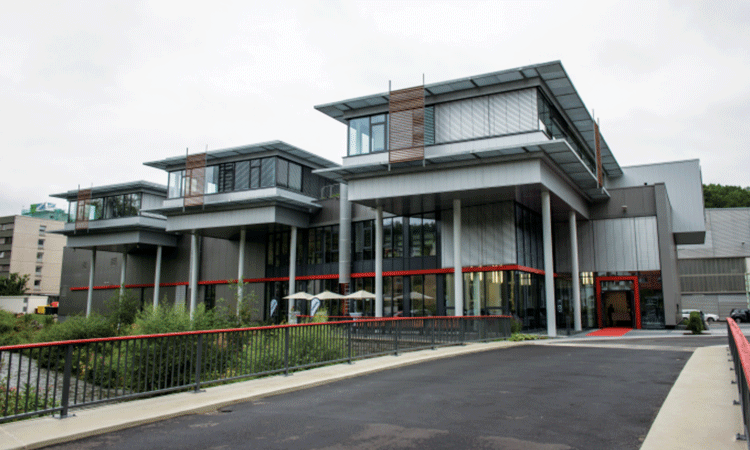
The official opening of the BTC was held on 10 July 2014 in Siegen, Germany, and approximately 40 engineers coming from different sites of our organisation have since moved into the building. The number of engineers working in the BTC is growing gradually according to the tasks to be fulfilled. The introduction of the BTC was not a ‘big bang’ regarding the way of working so far; we plan to build on our existing international network with sites in Siegen, Derby (United Kingdom), Winterthur (Switzerland), St. Bruno (Canada) and Crespin (France) but we will go for the next step in order to streamline our product engineering. The BTC is the future heart of our engineering community, and is focussed on:
- Creating new products until concept design stage
- Active managing of existing and new platforms
- R&D activities on component level together with external partners
- Innovation activities
- Testing (in parallel to the development and also for homologation purposes).
The BTC is closely linked to the aforementioned application sites where we are executing customer contracts.
Testing and accreditation – Requirements for accreditation
Accreditation and certification is an old but genuine requirement for test laboratories to convince the customer about the quality of the test work. In each EU-country there is one accreditation body, and for Germany this is the Deutsche Akkreditierungsstelle GmbH (DAkkS).
To get approval as an accredited test laboratory the essential requirements published within the EN ISO/IEC 17025 ‘General requirements for the competence of testing and calibration laboratories’ have to be managed. The requirements of the norm are divided into two blocks: management requirements; and technical requirements.
The management requirements cover the structure of the organisation and the process around the test, for example: document control, approval and issue; review of requests, tenders and contracts; monitoring of corrective actions; and internal audits and management reviews.
The technical requirements cover the test itself and the processing around the test, for example: qualification of the personnel; test methods and validation; estimation of uncertainty of measurement; equipment, calibration methods; and reporting the results.
A major requirement for the accreditation test laboratory is to show its independence from the business; for instance from the production of bogies. That will be solved by arranging the test laboratory directly under the Head of Bogie Engineering (Heiko Mannsbarth) with escalation line to the Member of Bombardier’s Executive Board (Dr. Susanne Kortendick).
All these requirements have to be documented in a detailed and structured manner within a Quality Manual. Regular audits with internal and external auditors will control the process.
Despite the great effort to get an accreditation Bombardier Bogies decided to go that way.
The accreditation process starts with the fatigue axle and wheel test rig. The bogie frame fatigue test rig will follow.
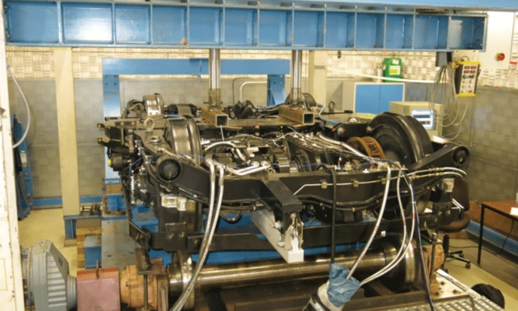

The roller rig to test a complete bogie and check the dynamic reaction
of the attachments
Test equipment
Recently installed are the following test arrangements:
Roller rig
This rig has a driven roll which is easy to change to simulate a corrugation rail or a wheel flat or to use an ideal roll. That gives the possibility to test a complete bogie with all attachments to test its reaction against such impacts from the rail or the wheel. During that test the speed can increase continuously to find resonance reactions of bogie attachments. Normally during such tests the bogie and its attachments are equipped with strain gauges and accelerometers. If resonance frequencies with unacceptable amplitudes are found, an appropriate solution can be easily installed and the improvement can be tested.
This test rig is also able to run a complete dynamic wheelset test with vertical and lateral forces. That could be done as a fatigue test or for special reasons also as a crack propagation test.
The test rig is also often used for identifying vibration or acoustic problems from gearboxes and bearings, etc. which could occur during operation or be identified during overhaul.
This roller rig is an easy test rig, but very effective; it’s a multipurpose test rig.
Resonance pulser
The resonance pulser can run a dynamic load of +/-125kN. It is a one-direction load pulser. The normal operation frequency is between 30 to 70Hz depending on the stiffness from the specimen. This means that during a run of 10 hours, approximately two million load cycles can be run. This test rig is used for testing a set of samples to check material quality, different welding, improved detail, develop a Wohler line for special material with special treatment (shoot blasted, TIG dressed, hammer peening PIT) and so on. It is often used for service business to develop small repair solutions. Because of the high test frequency this test rig supports us to develop very economical solutions.
Fatigue axle and wheel test rig
This test arrangement also works with the resonance of the test specimen but with a horizontal rotating mass which produces a ‘run’ around the bending of the standing axle. The applied bending moment increases from the axle’s top end where the rotation mass is fixed to the claimed wheel at the bottom. For the proof of axle body stress or the wheel seat, a stiffer wheel with an increased wheel web is used to increase the resonance frequency but also to prevent the original wheel web from overload. Because of the increasing bending load it is the normal case, that with such tests, only the axle body in the near of the wheel seat can be tested. If other regions of the axle body (e.g. bearing or gearbox cross section) should be tested special test arrangements have to be developed. In addition to the test of the axle itself this test rig could be used in the same way for the test of the normal wheel. By doing this the stress in the wheel web have to be measured. The tests of axles and wheels are described in EN13260/EN131261/EN13262.
Additionally, this test rig is able to run crack propagation tests of 1:1 axles. Therefore at the highest loaded axle body position a sharp notch has to be brought in. For this test the axle will be loaded by the real load spectrum which has to be measured during the real train operation. The start of the crack propagation will be identified and the crack increase will be measured by special crack strain gauges. This specific strain gauge has a distance of 0.1mm and many individual wires. Due to the crack increase, wires will be cut and therefore the strain gauge will change its electrical resistance so that this can be measured which gives an indication of the crack propagation. This test is used to define the ultrasonic inspection interval for railway axles.
Fatigue bogie frame test rig
To get an operation approval of a train, the bogie frame has to pass four development steps according to EN13749. Two of these are static loading tests and the dynamic or fatigue test. These tests have to be done in a test laboratory. Under series condition, a produced bogie frame will be loaded in a first test with static loads and load combinations. The bogie strain will be measured with strain gauges. The main loads like vertical, lateral, track twist and also the specific loads like brake load, damper, motor loads, etc., have to be measured and combined. Loads which represent the normal operation and exceptional loads have to be tested. The measured stresses have to be checked compared to the permissible stresses. The loads will be applied by hydraulic cylinders which could also be used for the dynamic test. Within this test step, the in-service loads have to be applied with the given load cycles. Three load steps with increased loads and 10Mio cycles have to be successfully completed. After each load step, the bogie frame has to be crack-checked by NDT (Non Destructive Test). Only small cracks which are not critical during service are allowed at the end of the third load step.
This test rig can be started within the next month if the cooling system for the hydraulic is finally completed.
Tilt and bogie system test rig
To get deeper knowledge of the bogie behaviour under operational conditions, the real bogie system parameters are needed. The bogie is built form many individual parts like springs, rubber metal elements, linkages, dampers, cables, primary and secondary level, etc. To find out and prove how the individual parts and effects act together in a complete bogie, a test rig was created by Bombardier. Here we’ve the possibility to study the system behaviour during tilting the bogie with +/- 12 degree. Therefore the bogie is loaded with real masses to simulate the carbody weight. The height of the loaded mass can be moved also in the height so that different carbody centre of gravity heights could be adjusted.
On track measurement
To gain knowledge of the in-service on track acting loads strain gauge measurements of the loaded structure are very common. Such measurements are also required to validate the bogie frame structure according to EN13749. There exists long experience of the test teams to perform this on track measurements. This is often used for identification of problems which occur during service. There could be a maximum of 200 measuring channels (strain gauges, displacement sensors, accelerometers) applied.
Outlook
Due to obvious reasons we can’t provide detailed information regarding our product development strategy. But we can state that having focused recent past years on the FLEXX Speed platform (very-high-speed bogies for China and Italy); FLEXX Eco platform (on-board bearing bogies for Metro Stockholm, Metro Riyadh, Intercity trains for Crossrail); FLEXX Power platform (locomotive bogies for DB AG); FLEXX Tronic Wako platform (bogies for roll compensation for SBB double-deck trains) we are now concentrating our activities on FLEXX Urban and FLEXX Metro applications.
The BTC will be a long-term migration project for our Business Unit Bogies. The BTC will be our link to the outside world, a place known by our customers, homologation institutes, the academic world and our suppliers. It will be an attraction for new talents and new ideas.


