A new process for the aluminothermic weld repair of discrete rail surface defects
Posted: 3 December 2008 | | No comments yet
Isolated rail head defects formed under traffic, detected either by visual inspection or ultrasonic flaw testing, can significantly reduce the service life of rails if not managed correctly. Surface initiated defects account for approximately 50% of all defects removed from Network Rail (NR) Infrastructure. These are predominately made up of squats from rolling contact fatigue and wheelburns caused by the heat introduced to the rail surface by friction between the rail and wheels during acceleration transforming the surface due to localised overheating leading to surface spalling and cracking.
Isolated rail head defects formed under traffic, detected either by visual inspection or ultrasonic flaw testing, can significantly reduce the service life of rails if not managed correctly. Surface initiated defects account for approximately 50% of all defects removed from Network Rail (NR) Infrastructure. These are predominately made up of squats from rolling contact fatigue and wheelburns caused by the heat introduced to the rail surface by friction between the rail and wheels during acceleration transforming the surface due to localised overheating leading to surface spalling and cracking.
Isolated rail head defects formed under traffic, detected either by visual inspection or ultrasonic flaw testing, can significantly reduce the service life of rails if not managed correctly.
Surface initiated defects account for approximately 50% of all defects removed from Network Rail (NR) Infrastructure. These are predominately made up of squats from rolling contact fatigue and wheelburns caused by the heat introduced to the rail surface by friction between the rail and wheels during acceleration transforming the surface due to localised overheating leading to surface spalling and cracking.
Currently, these defects are removed by re-railing or when repaired, are done so by manual metal arc (MMA) welding. Both methods are time consuming with re-railing usually requiring the stress free temperature to be restored and MMA repair prone to introducing further defects such as slag inclusions and stop/start porosity.
In response to the demands for improved track availability with reducing track access opportunities and a need to introduce maintenance cost reductions innovative solutions were sought to enable defects to be removed in a more efficient manner.
It is expected that the HRW process can be successfully applied to 5000 to 6000, 60 to 70% of all isolated surface defects.
In conjunction with NR, Thermit Welding (GB) Ltd (TWGB) has developed an aluminothermic weld repair process for the repair of these defects.
The process has been designed to cover a range of rail sections from 54 (109 and 110lb) to 60 kg per metre in both 220 (700) and 260 (900) grades.
Background
Originally, TWGB commenced the development of an aluminothermic head repair weld in liaison with BR Research and the Director of Civil Engineering. Development was suspended partly as a result of problems with weld integrity but principally because of strategic constraints of requiring the repair to be made between traffic. As all aluminothermic welding is now undertaken under a full track possession, interest in the process was renewed because of the perceived productivity and reliability benefits offered by the process over MMA repair or the removal of short lengths of rail containing defects and replacement with welded in closure rails.
The process was developed with particular attention paid to minimising costs and wherever possible aligning the method with equipment and welding practice used for the conventional SkV-E welding process commonly used as standard in the UK.
NR required a fast, reliable repair method leaving a sound repair with similar hardness and wear properties to the parent rail. The finished repair also had to be fully testable using conventional pedestrian and train-based ultrasonic procedures.
By the successful adoption of these objectives, NR and TWGB has developed the HRW to incorporate:
- Rapid defect removal by oxy-fuel gas cutting and grinding
- Conventional low pressure preheating – standard SkV-E parameters
- Single Use Crucibles
- Standard NR approved Thermit portions
- Normal Thermit welding, trimming and profile grinding practice
- Adoption of as much standard welding equipment as possible
The process has been designed as a quick, cost effective alternative to conventional MMA repairs, with multiple repairs possible within a normal welding shift.
The process also enables significant surface defects to be removed without the need for the installation of a short closure rail requiring two standard aluminothermic welds and re-stressing to achieve the required stress free temperature.
Further benefits are obtained with improved alignment as conventional rail welds can lead to minor misalignments or a mismatch of head or sidewear which needs to be catered for during the installation of a closure rail.
UK trials commenced with a limited number of defects being removed in Scotland which highlighted a susceptibility to suffer small defects particularly in early pre-concast rail. Process procedures were revised with the preheat time lengthened to improve the level of fusion between the rail and the weld. This greatly increased the level of fusion and eliminated the presence of the small defects seen with the initial trials.
In parallel with the trials, training material was also developed for the instruction of existing welders and non-destructive testing (NDT) personnel to enable them to undertake the repair process and carry out final weld inspection.
Nationwide trials have now commenced with a programme developed to install a further 250 welds for further evaluation. The results of these trials will then be used to maximise the applicability, optimise the repair process, and determine the level of post weld NDT that may be required leading to full acceptance for widespread national use.
Repair method
Details of the scope of the HRW are given below with dimensions of the defects that are repairable with the process (shown in Figure A).
Typical timings for the stages of the HRW process are as shown in Table 1.
Preparation
Accurate location of the centre of the defect is essential to effective removal:
Ultrasonic inspection is used to establish and record the defect length using a 0° probe (including the visible length of the defect) and the defect depth using a 70º probe. The length and centre of the defect is clearly marked on the field side of the rail head using a scribed line on a semi-permanent (paint) background.
Ultrasonic inspection is used to record:
- Depth of rail head
- Rail profile and material grade
- Track type; S&C, plain line
- Type & size of each defect, number of defects and distance between each defect
- Component type; plain rail, arc repair or flashbutt weld
Accuracy of inspection is essential if the full benefits are to be delivered.
The area to be repaired is marked on the rail, and excavated using a purpose designed oxy-fuel gas cutting template and torch.
Size of defective area that can be repaired:
- Full head width
- Up to 70mm (95mm after additional grinding) length
- Depth up to 35mm (depending on rail head wear)
The flame cut surface is ground to prepare the surface for NDT using magnetic particle inspection. If cracking is still detected the excavation can be extended to maximum allowable dimensions. If any cracks remain after the excavation that cannot be ground out, the repair process is continued and the repair reported as defective by the welder, emergency clamps fitted and the weld subjected to NDT. If the weld is subsequently reported as being clear of defects the clamps are removed with no further action required, or if still found to be defective, the repair removed with a conventional closure rail.
Final excavation – 75 to 95mm in length.
Rail Alignment
The rail fastenings are removed from two sleepers either side of the repair. Alignment devices or wedges are used to raise the repair area so that the rail is lifted with reference to the nibbed edge of the 1 metre straightedge.
For line speed <100 mph: lift = 0.5mm over 1.0m. For line speed >100mph: lift = 1.0mm over 1.0m, see Figure 4.
Assembly of the welding equipment
Most of the equipment is the same as that used for the standard SkV-E aluminothermic process. The rail is released from its fastenings either side of the repair area, and raised using wedges to produce a central lift of 0.5 – 1.0mm over a 1 metre span. A standard universal mounting and preheater mounting is fitted and the preheater height checked.
Preheater height: 70mm above centre of excavation.
The HRW moulds are checked for fit – minor adjustments may be made to accommodate head wear – and inserted into their shoes. The moulds are sealed to the rail with traditional luting materials.
The central core plug is tested for fit and placed by the repair.
Preheating
Apart from the special HRW preheater, the process uses standard preheating equipment, and conventional SkV oxy – propane pre-set pressures:
- Oxygen: 3.0 bar, Propane: 0.7 Bar
- Preheat time: 3.0 minutes
Welding
On completion of the preheat, the burner is removed, the plug is fitted and the Single Use Crucible (SUC), pre-charged with the Thermit® Portion is positioned between the locating pegs on the mould shoes and ignited. On completion of the reaction, the Thermit steel automatically discharges into the moulds.
Solidification and Profile Finishing
The welded repair is allowed to cool for 6.5 minutes, after which the excess material is removed using an aluminothermic weld trimmer. After a minimum period of 30 minutes, the rail is fastened down, and the trimmed surface ground to profile.
Technical specification
The Thermit® HRW process has initially been approved by NR for a limited trial installation in order to fully assess the reliability and benefits offered by the process. As part of the original development of the process test weld repairs have been subject to radiography and ultrasonic inspection to prove that original defects had been removed and that the repair weld is defect free.
Weld metallurgy and hardness
The resistance to wear across the weld is influenced by the variation in hardness across the weld and heat affected zone (HAZ).
The HRW process uses standard welding portions and produces a narrow HAZ on the running surface which helps minimise preferential wear shown in Table 2.
Strength (Bend Test)
Results from testing HRW welds in three point, slow bend test with the head in tension between 1.0m centres are shown in Table 3.
Final profile assessment and alignment tolerances
The weld shall be ground to the finished profile prior to final inspection which shall be carried out with a 1 metre straightedge with the repair central. The finished profile shall conform to the tolerances shown in Table 4. The smoothness of the ground surface across the weld is checked with a 200mm straightedge and feeler gauges. The maximum gap between the running surface and the 200mm straightedge shall be less than 0.2mm. The maximum gap measured along the running edge with a 1 metre straightedge shall be +/- 0.5mm.
Ultrasonic inspection
We have investigated how current ultrasonic testing procedures would respond to the repairs. NR has undertaken ultrasonic inspections of the finish ground repairs to determine the resultant responses from both the Sperry Roller Search Unit used for pedestrian ultrasonic inspection and the Ultrasonic Test Train. Tests showed that a full rail bottom echo could be maintained indicating that the weld repair was transparent to ultra-sound. Further tests were undertaken using specifically developed procedures using hand 0, 45 and 70 degree probes to determine how ultrasonic testing would respond to defects lying in and below the repair. We have also carried out extensive testing to make sure that the relatively coarse grain structure of the repair did not mask the presence of any remaining or developing cracking. Test pieces were prepared with specifically sized holes drilled beneath the repair weld representative of actual defects. Subsequent ultrasonic inspection of these specimens showed that the drilled holes could be accurately sized through the repair weld metal with confidence. Revised U18 ultrasonic procedures have been developed to carry out detailed inspection and assessment of the weld repairs after installation.
Future developments
The development of the HRW process has continued with TWGB to provide an oxy-acetylene alternative preheat procedure for use in tunnels/confined areas where propane fuel gas is prohibited. Initial trials of this process has given encouraging results from which it is hoped that formal approval will soon be granted.
Additional work is being undertaken to look at increasing the length of defect that can be removed by utilising overlapping repairs.
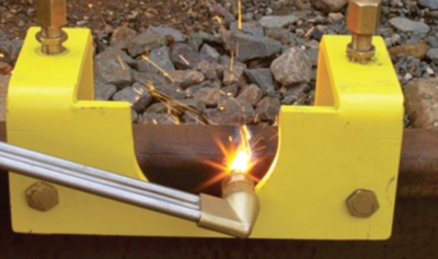

Figure 1: Oxy-fuel gas cutting of the excavation
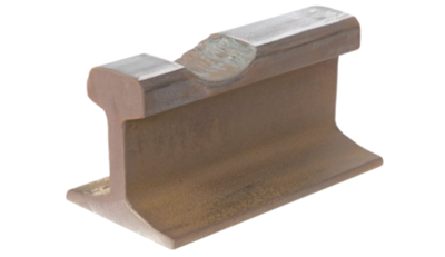

Figure 2: Finished flame cut excavation
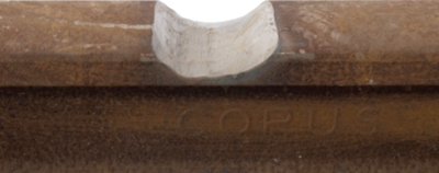

Figure 3: Finish ground excavation
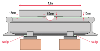

Figure 4: Rail alignment and lift prior to welding
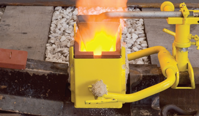

Figure 5: Preheat in progress during HRW installation


Figure 6: Final rail profile tolerances


