Vibrational accelerated long life and shock tests on Eurotunnel’s pagoda structures
Posted: 13 December 2015 | Estibaliz Muñoz Recarte, Pierre-Louis Percy | No comments yet
Due to the dynamic and aerodynamic effects of rail transit through tunnels, and as reference in this article to lorries loading and unloading on Eurotunnel wagons, railway structures are suffering forces which can potentially lead to fatigue failures.
Railway engineers have tried to design structures that can withstand these negative forces, and now there are several standards that give guidelines for designing and testing main railway structures in terms of fatigue – but, they also consider exceptional events such as accidents or collisions. Fulfilling these standards is critical for determining safety aspects prior to commissioning newly-designed railway wagons for commercial operations. Pierre-Louis Percy from Eurotunnel1 and Estibaliz Muñoz Recarte from CETEST2, explore further.
Standards EN12663 and EN13749 establish structural requirements for bogie frames and carbody shells respectively. In these standards, apart from main loads, loads on structural supports due to inertial effects of devices attached to them are also defined. These loads are calculated taking into account maximum and service acceleration levels established by the standards for each direction.
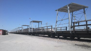
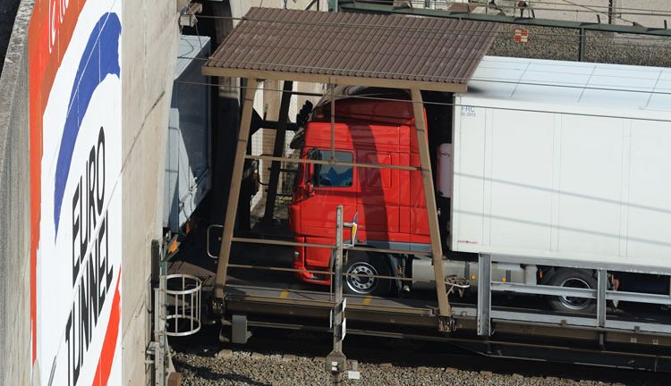
Figure 1: Tested item mounted on wagons
CETEST2 – an independent test laboratory – has several test benches to carry out these kinds of tests, including three configurable test benches for bogie frame validation according to EN13749, with the capacity to apply multiple static and dynamic loads on the bogie frame. A specific test set-up is designed for each bogie frame depending on the considered loads for each case, controlling actuators one-by-one or by bogie frame load component. CETEST also has two test benches to develop carbody shell validation according to EN13663, and two additional movable test benches to carry out these kinds of tests on customer’s facilities, therefore avoiding structure shipment.
The aforementioned standards consider the inertia influence of the attached devices over the main structure, but do not consider requirements for the devices themselves nor the influence of its dynamic behaviour. The standard EN61373 covers the requirements for random vibration and shock tests to be fulfilled by pneumatic, electrical and electronic devices mounted on railway units. Three different tests are specified: functional test; long life test; and shock test.
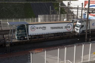
Figure 2: A loaded wagon
Severity levels and frequency range change depending on weight and location of the device (axle, bogie or carbody). The goal for ‘functional test’ is to verify that the devices functioning are not affected by the applied acceleration levels which are representative of those expected in service. On the other hand, the ‘long life test’ simulates the damage suffered by the device for its operational life. Severity levels on this case are set from functional acceleration levels amplified by a factor to generate equivalent damage in a five-hour test. According to this standard, the device should also withstand a ‘shock test’ in the three main directions.
CETEST has successfully developed a test based on EN61373 on a 6 DOF (Degrees Of Freedom) shacking table with a control band up to 60Hz. The structure subjected to this test is a pagoda mounted on Eurotunnel’s HGV (Heavy Good Vehicles) wagons transiting between France and England – known as the world’s busiest railway line.
The structures are mounted on freight wagons crossing the tunnel loaded with trucks. Their goal is to ensure maximum gauge and, at the same time, avoid aerodynamic effects that could damage the tarpaulins on different categories of HGV. Figures 1 and 2 show the tested structures.
The goal of the project was to validate the new design of the pagoda with a test considering the dynamic effects due to trucks and track, but also the dynamic response of the pagoda itself. Therefore, a test procedure providing definition of an actuation that could reflect the excitation levels and its distribution on the frequency domain was considered necessary.
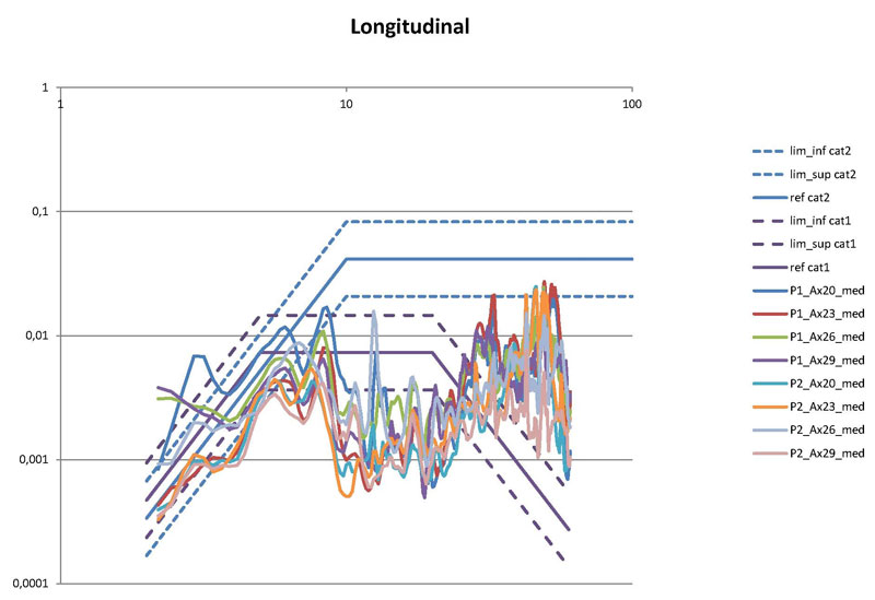
Figure 3a: Service data vs functional data proposed by the standard
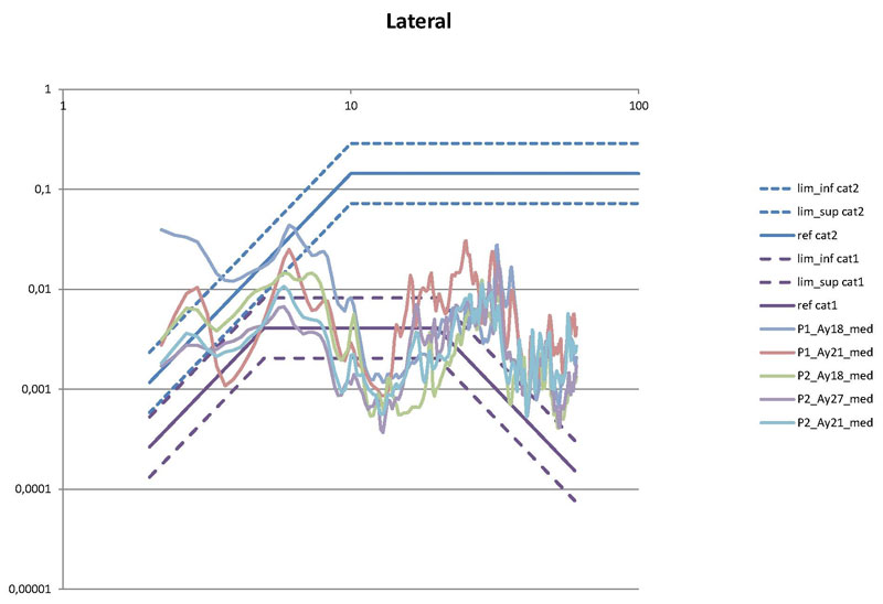
Figure 3b: Service data vs functional data proposed by the standard
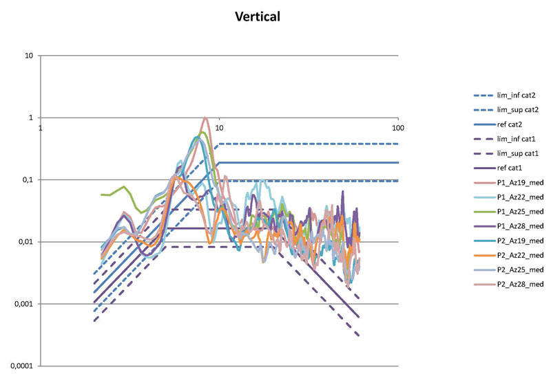
Figure 3c: Service data vs functional data proposed by the standard
In collaboration with CIMES3 and Eurotunnel, CETEST defined the requirements and developed a test for the pagoda’s new design validation, and several steps were needed for project development.
Step A: establishing a study of on-board gathered data and test requirements
A preliminary study of the accelerations suffered by the pagoda was developed by CETEST out of the on-board data submitted by Eurotunnel. Four accelerometers were installed on fixing points of the structure over two pagodas (old design) and several service trip data was acquired. The study of the data revealed a number of things, including:
- The main damage sustained on the pagoda was due to dynamics below 50Hz.
- According to the standard EN61373, the category level of the structure mounted on the body is 1A, but in this case as the vehicle has a unique suspension level, it should be considered as category 2. Following guidelines on Annex D, functional acquired acceleration levels were calculated and compared to those proposed by the standard. Figures 3a, 3b and 3c a comparison of the functional levels defined by the standard for category 1A and category 2 with those acquired in service for the three directions (distribution on the frequency domain is also considered). In general, acceleration levels suffered by the pagoda are between those proposed by the standard for category 1A and category 2.
- Considering that the acceleration suffered by the structure is between category 1A and 2, that the weight of the structure is higher than 1.250kg and that the damage content is below 50Hz, the frequency range established for the test is 2-60Hz.
- Different frequency ranges were established for simplified functional mean ASD (Acceleration Spectral Density) calculation. This new shape allowed better characterisation of the simplified functional ASD shape to the data gathered on service, and therefore, similar energy distribution on the excitation frequency range. These simplified ASD levels were considered as functional ASD levels for test development (see Figures 4a, 4b and 4c).
- Following guidelines on Annex A5 of the standard, the acceleration ratio needed to reproduce complete life on five hours test was calculated. Above showed ASD shape and levels multiplied by this factor were considered as the target ASD for long life test.
- From test proposed by standard EN61373, just long life and shock tests were considered. For shock test requirements, acceleration levels established by the standard EN13749 were considered.
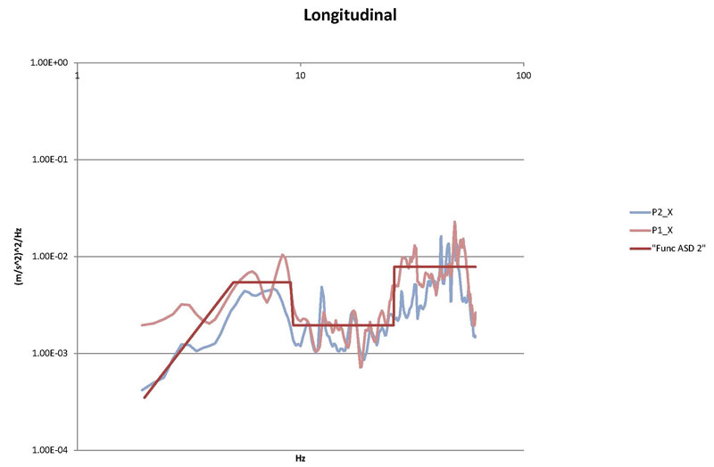
Figure 4a: Modified shape for functional ASD characterisation
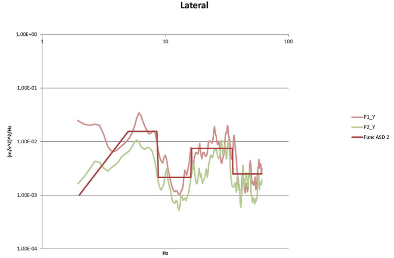
Figure 4b: Modified shape for functional ASD characterisation
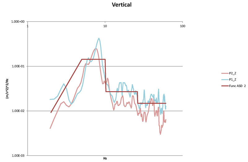
Figure 4c: Modified shape for functional ASD characterisation
Step B: damage calculation (CIMES)
Once the long life ASD and shock levels were defined, CIMES performed a dynamic calculation to account for damage generated over the pagoda during the test. The results obtained in this calculation showed that the pagoda would not suffer failure during the tests.
Step C: tooling design
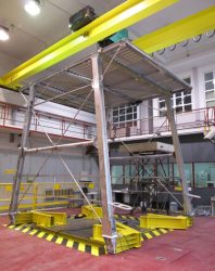
Figure 5: Pagoda mounted on a test bench
The pagoda dimensions are bigger than the dimensions of the shaking table used for the test. Therefore, CETEST needed to design and manufacture some tools to accommodate the pagoda on the test bench. Apart from fatigue resistance considerations, the design took into account natural frequencies of the devices to avoid control problems during test execution.
Step D: test development
During test development, acceleration and strain measurement at different points was performed. For table control, four accelerometers were installed on each pagoda fixing point, therefore ensuring that the desired ASD was induced on the pagoda. Obtained ASD compared to the desired ones are shown in Figures 6a, 6b and 6c. At the end of the test, magnetic particle inspection was carried out in order to detect cracks.
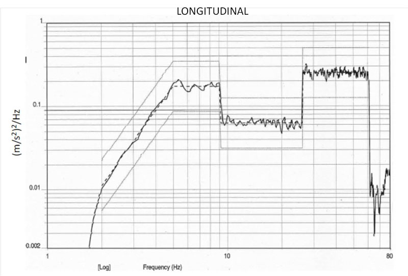
Figure 6a: Test bench response
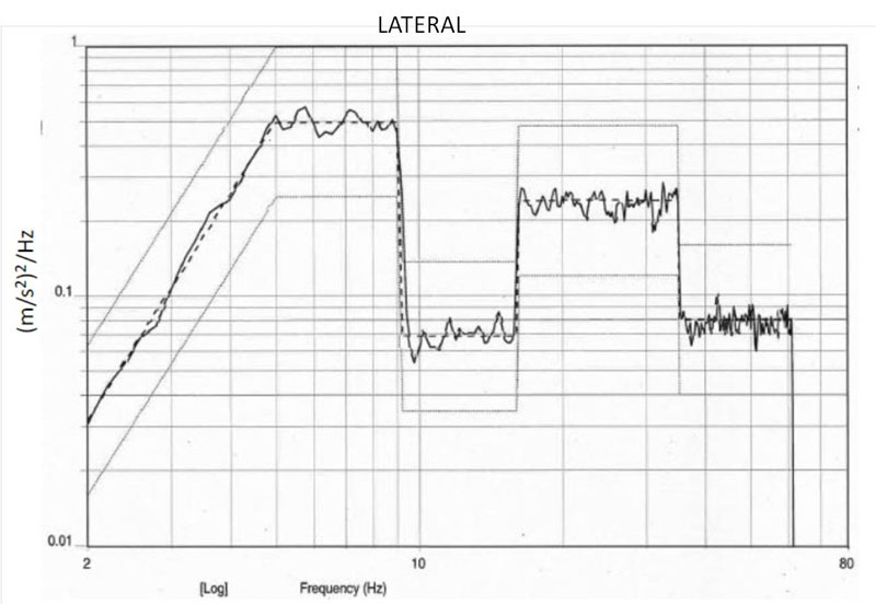
Figure 6b: Test bench response
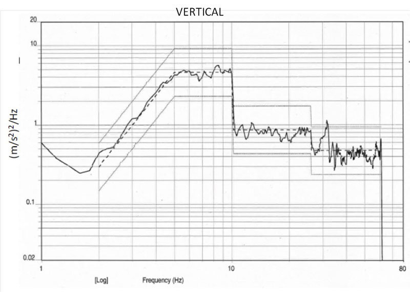
Figure 6c: Test bench response
Step E: damage calculation (CETEST)
The data of the strain gages was post processed to calculate damage generated by the test on the pagoda. The calculation process is summarised in Figure 7.
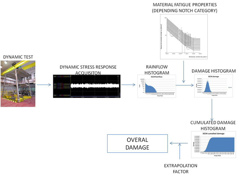
Figure 7: Damage calculation process
The new pagoda design successfully passed the established test requirements. Damage calculation performed from data acquired during the test over the most critical instrumented points showed no failure of the structure. One rake, composed of 16 wagons, each one equipped with one pagoda, was in commercial service from 14 June 2014 completing more than 350,000km. Then, after four months of services without failures, nine rakes were equipped in October 2014, which now represent, in global terms, more than two million kilometres in operational service confirming the results previously obtained in the tests.
The development of this test is a clear example of collaboration and research between different entities: CIMES (a consultancy and engineering services company), Eurotunnel (as holder of the Channel Tunnel concession) and CETEST (a test laboratory). A complete process on a new structural design was carried out by these three companies: initial and subsequent revisions were worked on until a final design emerged based on calculation results (CIMES), test specification and execution (CETEST) and new structure fabrication and implementation on service units (Eurotunnel).
Biography
 Pierre-Louis Percy holds a degree in industrial engineering and is currently employed as Project Manager for Eurotunnel. As sole authority for the overall development process of new products, Pierre-Louis is also the technical liaison point for Eurotunnel’s numerous subcontractors and suppliers. Managing the collaboration and coordination of diverse railway specialists such as CETEST, CIMES, TECHNI-INDUSTRIE, INDUSTEAM and APAVE has allowed Pierre-Louis to succeed in the challenge of fabricating, producing, testing and installing of 150 pagodas in only one year.
 Estibaliz Muñoz Recarte holds a degree in Industrial Engineering. She currently works as a Senior Engineer in the area of structural testing at CETEST, and her main areas of involvement include resistance and durability of bogie frame structures and substructures. She also takes part in the design and set-up of test benches, merging mechanical design with control systems.