Understanding the phenomena of train aerodynamics
Posted: 26 September 2013 | | No comments yet
In very broad terms, railway aerodynamic effects increase in severity with the square of the speed of the train – and historically came to become of concern as the speed of passenger trains increased beyond around 100km/h. In the first instance, attention was paid to reducing the aerodynamic drag of trains, both to reduce fuel consumption and to enable higher speeds to be achieved. As long ago as 1938, tests were being carried out at the London, Midland and Scottish Railway Research Centre at Derby to measure the aerodynamic drag of Coronation class steam engines, and to investigate smoke dispersion around the locomotive. But a whole series of other issues rapidly became apparent as train speeds of 200km/h or more became common.
The existence of severe pressure transients in tunnels that caused considerable passenger discomfort was investigated in both Europe and Japan. Indeed in the UK aerodynamic speed limits were imposed on some narrow Victorian tunnels where the pressure transients were found to be very severe at higher train speeds.
In very broad terms, railway aerodynamic effects increase in severity with the square of the speed of the train – and historically came to become of concern as the speed of passenger trains increased beyond around 100km/h. In the first instance, attention was paid to reducing the aerodynamic drag of trains, both to reduce fuel consumption and to enable higher speeds to be achieved. As long ago as 1938, tests were being carried out at the London, Midland and Scottish Railway Research Centre at Derby to measure the aerodynamic drag of Coronation class steam engines, and to investigate smoke dispersion around the locomotive. But a whole series of other issues rapidly became apparent as train speeds of 200km/h or more became common. The existence of severe pressure transients in tunnels that caused considerable passenger discomfort was investigated in both Europe and Japan. Indeed in the UK aerodynamic speed limits were imposed on some narrow Victorian tunnels where the pressure transients were found to be very severe at higher train speeds.
In very broad terms, railway aerodynamic effects increase in severity with the square of the speed of the train – and historically came to become of concern as the speed of passenger trains increased beyond around 100km/h. In the first instance, attention was paid to reducing the aerodynamic drag of trains, both to reduce fuel consumption and to enable higher speeds to be achieved. As long ago as 1938, tests were being carried out at the London, Midland and Scottish Railway Research Centre at Derby to measure the aerodynamic drag of Coronation class steam engines, and to investigate smoke dispersion around the locomotive. But a whole series of other issues rapidly became apparent as train speeds of 200km/h or more became common.
The existence of severe pressure transients in tunnels that caused considerable passenger discomfort was investigated in both Europe and Japan. Indeed in the UK aerodynamic speed limits were imposed on some narrow Victorian tunnels where the pressure transients were found to be very severe at higher train speeds. The stability of lightweight trains in high winds became an area of concern, particularly with the development of the Advanced Passenger Train, and accidents involving pantograph dewirement in high winds also became increasingly common and methods were derived for determining the correct spacing between cable supports to minimise this problem. The effects of high wind velocities in train slipstreams on workers at the trackside, passengers waiting on platforms, and, most particularly, pushchairs holding small children, caused largely by aerodynamically rough freight trains, also came to be of concern. As speeds increased still further to 300km/h and beyond, these issues became of increasing concern, and yet a further set of issues became apparent – sonic booms from the exits of railway tunnels, failure of trackside structures such as noise barriers due to fatigue loading by train pressure transients and the lifting of large ballast particles beneath trains causing damage to both trains and track. Today the range of aerodynamic issues that need to be taken into account in the design process for new trains and new routes is extensive. In Europe, considerable work has been carried out over recent years to develop standards and codes to aid in this process, and this has resulted in a series of codes of practice produced by CEN, and aerodynamic provisions in the Technical Standards for Interoperability (TSI) for both rolling stock and infrastructure.
The problems thus having been set out, obviously questions arise concerning how these issues can be addressed. A number of methods are available – each with their own positive and negative points. Full-scale tests can be used for the assessment of some effects, and these of course provide data that is ‘real’, although the operational difficulties in carrying out such tests are significant, and the environmental conditions (and in particular crosswinds) cannot be controlled. On the other hand, powerful compu – tational techniques are becoming available that enable the full flow field around trains, and the associated pressures and velocities to be calculated. However, train aerodynamic calcula tions are extremely challenging in technical and numerical terms and although these tools are becoming increasingly useful in certain areas, as yet they cannot be used to address the unsteady aspects of many train aerodynamic phenomena.
The third method is that of physical modelling. Physical modelling of trains has the advantage over full-scale testing in having controlled environmental conditions, but does result in a considerable number of modelling issues. If a conventional wind tunnel is used, the train will need to either be mounted on the wind tunnel floor on some simulation of railway track or on a suitable ground board, or above a moving belt. The high length/height ratio of the train results in a number of issues – first there is the practicality of fitting a full model train into a wind tunnel and of holding it in position above a moving ground plane. For stationary models, the boundary layer growth along the ground plane is considerable and at the rear of the train represents unrealistic conditions. Then of course there is the issue of scale modelling effects as the model scale trains have values of the major scaling parameter, the Reynolds number, much lower than would be found in reality, which has the potential to result in unrealistic flow fields around the models. For experiments to measure cross wind forces, wind tunnel tests on the leading vehicles are used extensively and the methodology is well-documented, and recommended in the CEN codes and the TSI documentation. The standard methodology uses low turbulence wind tunnel tests, with train models mounted on a suitable simulation of the track on a ground plane in the wind tunnel. Such a methodology does not model the effects of atmospheric turbulence and shear, or of vehicle motion above the ground, but it has been shown that it is a suitable standard technique for high-speed trains. For lower train speeds, accurate cross wind force determination requires the simulation of atmospheric effects, although such simulations are challenging.
However, there is another type of experi – mental technique that can be used for train aerodynamics – the moving model method – in which a moving model of the train is fired along a test track. Clearly this simulates the ground conditions more accurately than the wind tunnel, but at the expense of model complexity. A number of such rigs now exist around the world – for example at the University of Birmingham in the UK, DLR in Germany, and Central South University at Changsha in China, and essentially consist of a firing mechanism of some sort, an acceleration section, a working section and a braking section. The University of Birmingham TRAIN (Transient Railway Aerodynamics INvestigation) Rig is a highly versatile moving model rig that can be used for a wide variety of railway aerodynamic investigations. In broad terms, it consists of a 150m-long track along which model vehicles can be propelled, in both directions, at speeds of up to 75m/s. It is housed in a purpose built enclosure and has an overall length of 150m with a 50m-long test section. The models that are used are usually at 1/25th scale and are propelled along the track by rubber catapults. A cross-flow facility is provided adjacent to the test section to permit tests to be carried out on the effects of winds on vehicles and the influence of winds on vehicle slipstream flows. Photographs of the facility are shown in Figure 1.

Figure 1 The TRAIN Rig
For tests on trains in the open air, such rigs can make accurate measurements of train slipstreams and pressure transients that compare well with fullscale experiments – see Figure 2.
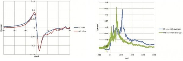
Figure 2 Comparison of pressure transients and slipstream velocities with full-scale experiments for ICE 2 train. The left-hand figure shows full-scale (FS) and model-scale (MS) pressure coefficients around the nose of the train. The right-hand figure shows FS and MS slipstream ensemble averages, scaled with the train speed – the difference in the position of the peaks being due to the different lengths of train.
They have also been used extensively for measurements in tunnels, where pressure time histories are required. For such tests to be representative of the full-scale situation, models need to be run at the correct Mach number which implies fullscale speeds, and moving model rigs can be used at speeds of up to 80 to 100m/s for this purpose. Tests with cross winds can also be made if a suitable cross wind generator is placed next to the track (see Figure 3), but here the measuring crosswind pressures and forces on moving trains results in complex and difficult experiments, with on-board balances or pressure transducers that need to withstand the high accelerations and decelerations involved. In general, the measurements on such rigs can be made with standard wind tunnel equipment, although very high sampling rates are required, particularly at the higher model speeds – up to 10,000 samples/second.

Figure 3 TRAIN Rig cross wind generator and instrumented model
Recent work on the TRAIN Rig includes EPSRC funded measurements of the slipstreams and pressure transients from Class 43 (HST) vehicles, for comparison with on-going full-scale on-train and trackside measurements; and research student projects on the effect of flow confinement on the flow around trains (such as hoardings, deep cuttings and overbridges) and on fundamental aspects of freight train aerodynamics (see Figure 4). More applied projects include the RSSB funded measurement of loads caused by a number of different train types on trackside structures for a UK national annex for a CEN code of practice; measurements of tunnel pressure transients as part of an EU project investigating the emission of sonic booms from tunnels at high train speeds; and measure – ments of train pressure loading and tunnel effects for high-speed rail operators in the UK and overseas.
Biography
Chris Baker is Professor of Environmental Fluid Mechanics in the School of Civil Engineering at the University of Birmingham and Director of the Birmingham Centre for Railway Research and Education, with wide ranging research interests in the fields of wind engineering, wind/crop interaction, road and rail aerodynamics, pollution dispersion and transport resilience in adverse weather. Chris was an undergraduate, postgraduate and Fellow at St Catharine’s College Cambridge, and has worked in the past for British Rail Research and Nottingham University. Chris is currently PI for grants of the order of £2.5 million from EPRSC, EU Figure 4 Freight train model on the TRAIN Rig and rail industry sources.
Issue
Related topics
Related organisations
Birmingham Centre for Railway Research and Education (BCRRE), University of Birmingham