Assessment of high-speed slab track design
Posted: 28 November 2006 | | No comments yet
Currently, all over the world, non-ballasted track concepts are being applied, although still at a moderate volume. If the low maintenance characteristics of slab track on open line are to be retained, great care must be taken to ensure that the subgrade layers are homogenous and capable of bearing the loads imposed. The slabs can be precast or poured on site. The most known tracks with precast slabs are on the Shinkansen line in Japan and Max Bögl slab track designed in Germany, while examples of the tracks with on site poured slabs Rheda 2000 (Germany) and various designs of an Embedded Rail Structure can be mentioned.
Currently, all over the world, non-ballasted track concepts are being applied, although still at a moderate volume. If the low maintenance characteristics of slab track on open line are to be retained, great care must be taken to ensure that the subgrade layers are homogenous and capable of bearing the loads imposed. The slabs can be precast or poured on site. The most known tracks with precast slabs are on the Shinkansen line in Japan and Max Bögl slab track designed in Germany, while examples of the tracks with on site poured slabs Rheda 2000 (Germany) and various designs of an Embedded Rail Structure can be mentioned.
Currently, all over the world, non-ballasted track concepts are being applied, although still at a moderate volume.
If the low maintenance characteristics of slab track on open line are to be retained, great care must be taken to ensure that the subgrade layers are homogenous and capable of bearing the loads imposed2. The slabs can be precast or poured on site. The most known tracks with precast slabs are on the Shinkansen line in Japan and Max Bögl slab track designed in Germany2, while examples of the tracks with on site poured slabs Rheda 2000 (Germany) and various designs of an Embedded Rail Structure can be mentioned2.
The main advantages of such structures are:
- Reduction of structure height
- Lower maintenance requirements and hence higher availability
- Increased service life
- High lateral track resistance which allows future speed increases in combination with tilting technology
- No problems with churning of ballast particles at high-speed
Supported slab track structures
If no bending resistance is required, both precast and on site poured slab track designs can be applied. Problems arise when such structure is built on soils where some settlements may be expected. In this case, there are mainly three ways of applying a slab track2:
- Using a slab with reinforcement at the neutral line (e.g. Rheda 2000). Since the bending stiffness of such slab is very poor, massive soil improvements are required which makes such slab structure financially less attractive
- Using a slab with reinforcement at the top and at the bottom of the slab, which improves the bending strength of the track structure. Various studies at TU Delft have shown that relatively high reinforcement percentages of about 1.5% for a B35 concrete are required1, 3, 4. On the other hand, only very limited soil improvements are necessary
- Using bridge or bridge like structures as a substructure in slab track design. The influence of bending of the bridge has a restricted influence on the bending stresses in the track slab.
In places with very soft soil, Rheda 2000 on Settlement Free Plate (SFP) is used, for example like on the HSL-Zuid (The Netherlands). A typical cross-section of such a structure is shown in Figure 2.1. Clear division between sub- and super-structure can be seen from this figure. The substructure consists of SFP’s (30m or 35m long) supported by piles, while Rheda-2000 forms the superstructure. The number of supporting piles of the SFP’s and their spacing are varied depending on the structural design. An important element of the slab track structure is a thin intermediate layer (plastic foil, Geotextile etc.), which is placed between the sub- and super-structures.
In Germany, a precast slab track system called Feste Fahrbahn Bögl (FFB) produced by Max Bögl GmbH is in use2. This system is to a large extent similar to Shinkansen track. A typical FFB structure consists of transversally pre-stressed precast slabs which are longitudinally coupled using force-transmitting joints. Such structures can be used on embankments, bridge structures, in tunnels and troughs. One modification of this structure built on a long bridge which is designed for a high-speed line section between Beijing-Tianjin (China) will be discussed later in this paper. The FFB (China) structure is almost 116km long. Approximately 12km of this structure is built on earth work and approximately 104km is laid on bridges. Each bridge slab has a length of 31.5m. The FBB (China) consists of the following elements:
- FFB precast slabs
- Grout layer
- Concrete support panel (SP)
- Intermediate layer (Geotextile + Foil)
- Bridge slabs
- Bridge supports
Another example of a pile supported slab track structure is a Neue Feste Fahrbahn (NFF) designed by ThyssenKrupp Gft Gleistechnik GmbH. A typical NFF track design is shown in Figure 2.5. The rails are mounted to a precast concrete frame, which consists of two slabs connected to each other. Each slab is mounted to piles by means of three short (transversal) bearers. It should be noted that the NFF structure investigated by TUDelft differs from the one shown in Figure 2.5, namely each transversal beam is rested on three piles, but the construction principle of these structures is the same.
Dynamic analysis of slab track
Analysis of the static and dynamic behaviour of a slab track under various loadings is part of a design process. Both short-term and long-term behaviour of a track structure should be analysed. The Railway Engineering Group at Delft University of Technology (TUD) has developed an approach for assessment of slab track design for high-speed lines. The approach is based on the dynamic analysis of a slab track and a number of performance factors calculated on the basis of the results of the dynamic simulations. In the subsequent section the main parts of the assessment procedure are described.
Vehicle-track model
The dynamic analysis of a vehicle-track interaction is performed using the program DARTS_NL developed at TU Delft. In order to reduce the computational effort the modelling is restricted to two dimensions (the vertical and longitudinal directions) and material behaviour is linear. A track structure is represented by a series of alternating hard and soft layers. The hard layers represented by Timoshenko beam elements can be used for modelling track structural components such as rails, sleepers, concrete slabs etc. The elastic interface layers are represented by distributed spring and damper combinations, which can be used to model rail pads, ballast (mats), elastomers etc.
A vehicle in DARTS_NL is modelled as a mass-spring system. An example of a model for a single car on a classical track is given in Figure 3.1. At present, one conventional speed and two high-speed train models are available in DARTS_NL, i.e. a Thalys, ICE3M and ICEMat.
Vertical rail geometry
Vertical rail level geometry is an important source of disturbances applied to a vehicle-track system and therefore it should be properly represented in the numerical model. The effect of both short and long wave irregularities must be included in order to obtain realistic results. In DARTS_NL there is a possibility to model the vertical rail level geometry using measurement data such as the one shown in Figure 3.2. However, recording cars, and in particular the conventional ones, lack long wave information (>25m). Therefore, a special vertical rail level geometry profile had to be constructed (Figure 3.3), combining the measured profile with artificial long wave irregularities (Figure 3.4). The combined profile has been used in the dynamic simulations of high-speed slab track structures.
Dynamic simulations
For analysis of the dynamic behaviour of slab track, the most representative part of it (approximately 250m – 300m) has been modelled. The most failure susceptible places in the structure (such as the joints between the concrete slabs and the bridges) should be present in the model, as it is shown for the FFB (China) track in Figure 3.5. A number of the dynamic simulations for Thalys, ICE3M and (in case of track sharing) ICEMat, travelling with the typical velocities of 90 m/s, 65 m/s and 40 m/s, has been performed.
After each simulation the following results had been collected:
- Front and rear accelerations of all car bodies of a train
- Wheel-rail contact forces of all wheels
- Displacements and bending moments of the concrete slabs of a track structure
The collected data are to be used in the track performance assessment shown later. On top of the previously discussed dynamic analyses results the effects of local dynamic responses due to short wave irregularities, such as poor welds, should be superimposed.
Assessment criteria
In principle, there are three major indicators to assess the performance of a slab track design. Some of these indicators are related to the limit values which are stated in HSL-South guidelines and Eurocode. The three indicators are discussed below.
Indicator 1: car body accelerations
Car body accelerations of trains play an important role in the assessment of passenger comfort. Generally, car body accelerations are low-pass filtered by the primary and secondary suspension. In HSL-trains, very resilient secondary suspension systems are used to further increase the low-pass filtering properties.
Accelerations experienced by passengers should not exceed quality level 2 of the UIC-513 standard. In the DARTS_NL simulations only vertical accelerations are considered, whereas the UIC-513 standards are based on weighted three-dimensional accelerations. With the help of some approximations the UIC standard could be converted to an admissible standard deviation for the vertical car body once acceleration has been established. According to this link the standard deviation of vertical body accelerations is 0.38 m/s2.
Indicator 2: wheel-rail interaction forces
Forces in the interface between wheel and rail should be limited to confine the superstructure as well as the wheel and rail wear. Similar to the car body accelerations, the contact forces increase due to deterioration of the vertical track geometry.
A simple way of expressing the dynamic effects is by using the Dynamic Amplification Factor (DAF). For contact forces the DAF is defined as the ratio between the maximum wheel-rail dynamic force and the static wheel load. In case of numerical simulations, measurements and recordings of the maximum value is not a very representative one. This is due to incidental rail irregularities and the contact force can increase tremendously as it was observed for rail joints and poor welds5.
As the dynamic force should in fact be considered as a statistical distribution, the maximum value has been replaced by its 95% probability, corresponding to two times the standard deviation (2σ). This estimation is considered to be more representative because the simulation time and vertical rail geometry are rather limited and arbitrary. Thus, the contact forces DAF is calculated as:
![]()
![]()
where
![]()
![]()
– is the estimation (95% probability) of the maximum wheel-rail contact force
![]()
![]()
– is the static nominal wheel load.
According to the HSL-South guidelines for a track design (HSL 600E 3.2.3), the dynamic amplification due to running trains is limited to DAF95 = 1.67. The Eurocode (ENV 1991-3:1995 6.4.3.2) also gives DAF95 limits, which are equal to 1.67 for a ‘carefully maintained track’ and the limit 2.00 for a ‘track with standard maintenance’. The vertical track geometry profiles used in the dynamic simulations had standard deviations of σ = 1.0 mm and σ = 1.5 mm, correspond to ‘carefully maintained track’ and ‘track with standard maintenance’ respectively.
Indicator 3: bending moments of concrete slabs
Bending moments that take place in the structure have to be considered with respect to structural strength and fatigue properties. The critical places in the structure have to be determined beforehand. Then checks on strength and fatigue can be performed efficiently. Generally the check on fatigue will be decisive in the analysis of long-term behaviour of a track structure. Some guidelines on fatigue analysis of reinforced concrete structures can be found in the Eurocode-2-2.
For example in the simulations with Rheda-2000, a piled slab with the connections of the jointed slabs over joints of the substructure was selected for a closer observation on strength and fatigue. Maximum and minimum bending moments in the jointed Rheda slab during train passages were used to perform the necessary checks.
For the slab strength analysis, the Dynamic Amplification Factor (DAF) of the bending moments was calculated for both positive and negative moments. The DAF for each group was then determined as the maximum dynamic value over the maximum static value. In case of the Dutch high-speed line, DAF values of 1.6 (between piles) and 2.19 (at piles) were achieved.
Numerical results
The presented approach for assessment of slab track structures has recently been applied to Rheda 2000 (HSL-Zuid), Neue Feste Fahrbahn and Feste Fahrbahn Bögle slab track (HSL China) which were described in the previous sections of this article. To give an impression of the dynamic simulations, an example of the results obtained for one of the HSL-Zuid track designs is shown in Figure 5.1.
Based on the analysis of the dynamic results, the following conclusions have been made:
- In all simulations, Thalys and ICE3M trains have shown an acceptable level of car body accelerations on all considered slab track structures, which does not exceed the required 0.38 m/s2
- The maximum DAF95 values of the wheel-rail contact forces calculated for normal and rough rail geometry were in relatively good agreement with the HSL and Eurocode standards
- The quality of vertical rail level geometry has a dominant influence on the dynamic responses such as vehicle accelerations and wheel-rail contact forces. For normal rail geometry (s[3–25m] ~~ 1.0 mm) reasonably good results have been achieved, but higher dynamic amplification can be expected if the rail geometry deteriorates. The results of the simulations have emphasised the importance of maintaining the vertical rail geometry on the required level
- Influence of the slab track superstructure on the dynamic responses was very restricted, while the influence of the substructure, such as pile spacing and bridge (piled slab) properties, was quite significant
- Rolling stock parameters especially damping have a substantial effect on the dynamic responses
Requirements for maintenance and construction
It is extremely important to carefully control the track geometry during construction as corrections afterwards are very difficult. Since a satisfactory level of car body accelerations and wheel rail forces had been achieved in combination with the applied vertical track geometry presented in Table 6.1, it was suggested to use this geometry also in the definition of track geometry standards for construction and maintenance.
Best practice in high-speed track design
Presently, high-speed lines are rapidly expanding, primarily in Asia and Europe. Spain (ADIF) is currently the largest investor worldwide with approximately €20 billion in the next five years6. For a new line, mostly systems of existing lines are copied, with ‘service proven’ being the key argument. This approach can be understood, but has a major drawback on technical innovations. The points below are trying to summarise best practice for the design of high-speed tracks:
- The Contractor should comply with the Contract
- The commissioning body is free to specify which standards and conditions should be applied
- It is common practice to have a Reference System, either an existing high-speed line, or a system worked out on paper which is also referring to service proven components (for instance fastening systems), or total designs
- Service proven is most of the times a necessary requirement, but never a sufficient requirement. Service proven means valid under the conditions for that specific line. In a new project often different boundary conditions will be applicable
- The integral structure should be fully analysed (detailed design) under the actual dynamic train loads and deformations applied by the supporting structure as specified in the Contract. It is common practice to use Finite Element Models
- Another argument for a detailed design is that new developments come up quickly and should be used if possible
- Testing of components like fastening systems is not necessary if certificates are available showing that a component has passed in earlier tests. For all constituents TSI-Infrastructure certificates conform EC Council Directive 96/48/EC have to be present. In addition Factory Admission Tests are mandatory. It should be emphasized that ‘Service Proven’ is by no means a valid argument which could supersede the TSI certificates
- In general fastening systems have to be tested for each country separately for ballasted track and non-ballasted track
- Basically there are two high-speed concepts originated from Japan and Europe. Rail fastening standards from Europe (CEN) and Japan (RTRI) are quite different due to a different rolling stock design. It cannot be assumed that a fastening which passes the CEN tests will automatically meet the Japanese requirements and vise versa. This problem was encountered on the new Taiwan HSL where Shinkansen track and BWG turnouts on Rheda 2000 were installed.
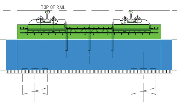

Figure 2.1: Typical cross section of Rheda 2000 on a Settlement-free plate (HSL-Zvid)
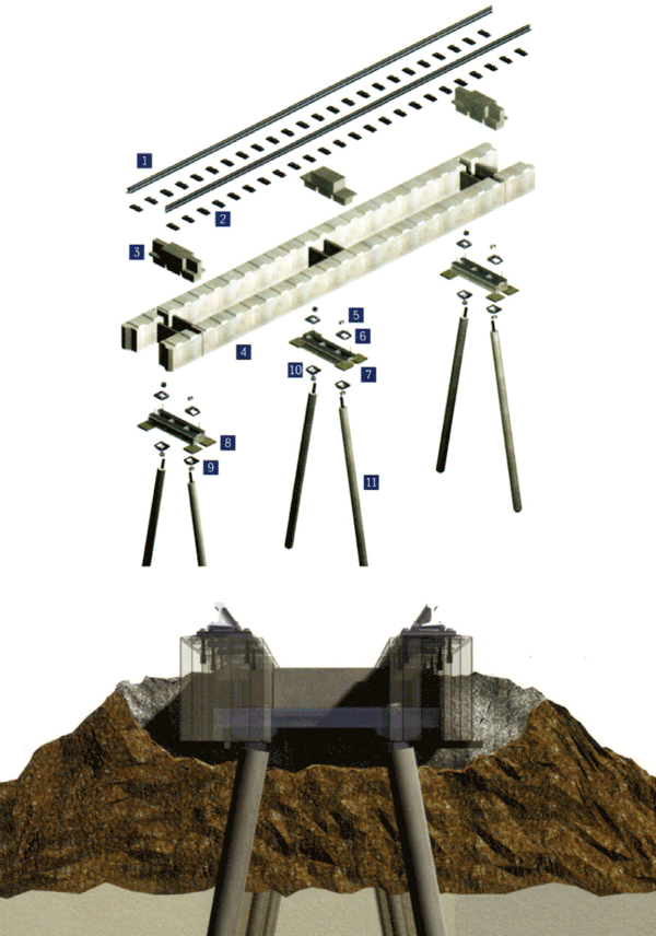

Figure 2.5: Constructional principle of NFF Structure
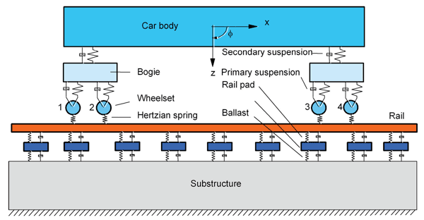

Figure 3.1: A vehicle track model in DARTS_NL
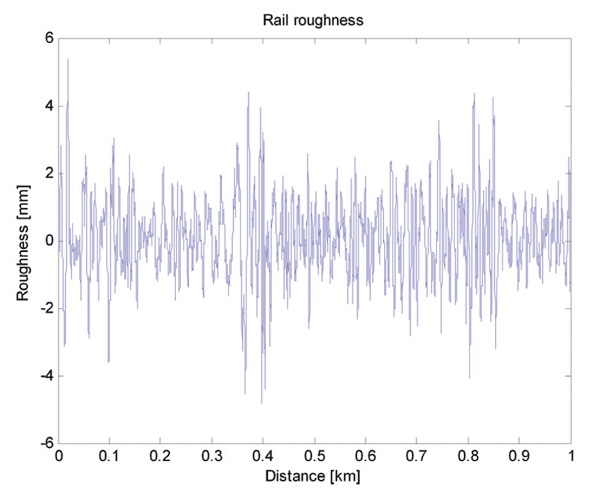

Figure 3.2: Vertical rail Level geometry obtained from a measurement car
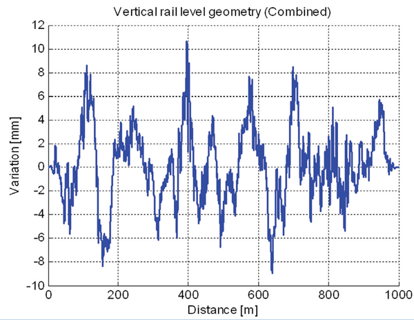

Figure 3.3: Combined vertical rail level geometry used in dynamic simulations
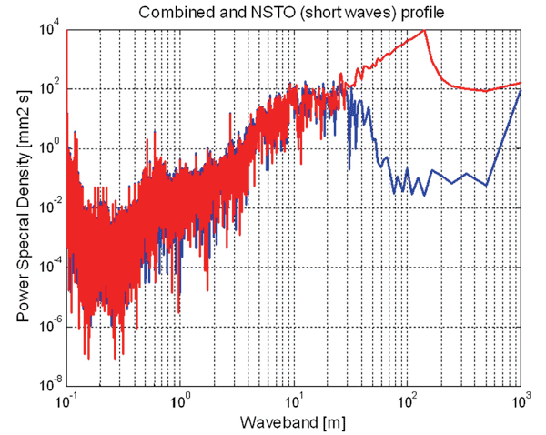

Figure 3.4: Power Spectral Density of measured (blue line) and combined (red line) vertical rail level geometry profiles
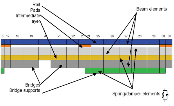

Figure 3.5a: A part of the FE model of FFB track


Table 6.1: Maximun variation (Umax) and () standard deviation of combined vertical rail level geometry profile
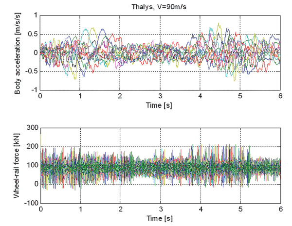

Figure 5.1: Example of results of the numerical simulations for HSL-Zuid (Thalys, 90 m/s)
References
- Esveld, C. (2001) Modern Railway Track. MRT-Productions, Zaltbommel. ISBN 90-800324-3-3 (www.eseld.com)
- Esveld, C. (2003) Recent developments in slab track. Global Railway Review, Issue 2, 2003. ISSN 1351 – 1599
- Esveld, C., Markine, V.L. (2003) Developments in High-Speed Track Design. Short paper Proceedings of International Association for Bridge and Structural Engineering (IABSE) Symposium on Structures for High-Speed Railway Transport, Antwerp, Belgium, August 27-29, 2003. pp.14-15 ISBN 3-85748- 109-91.
- Markine, V.L., J.M. Zwarthoed, C. Esveld, (2001) Use Of Numerical Optimisation In Railway Slab Track Design. In. O.M. Querin (Ed.): Engineering Design Optimization Product and Process Improvement. Proceedings of the 3rd ASMO UK / ISSMO conference, Harrogate, North Yorkshire, UK, 9th -10th July 2001. ISBN: 0-85316-219-0 (for text version), ISBN: 0-85316-222-0 (for CD-ROM version).Zwarthoed, J.M. (2001) Slab Track design: Flexural Stiffness Versus Soil Improvement. Proceedings of Rail-Tech Europe 2001 Conference.
- Esveld, C., Steenbergen, M.J.M.M. Steenbergen. “Force-Based Assessment of Weld Geometry”, Proc. 7th World Congress on Railway Research, Montreal, (2006)
- IRJ, September 2006, page 69-74


