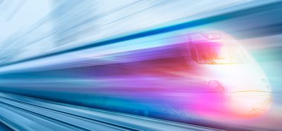
EMU V250 high speed train to connect Belgium to Holland
Posted: 2 March 2005 | | No comments yet
The EMU V250 train is designed for the high speed line (HSL) being constructed which connects Belgium to Holland. This is the first train fully compliant with the TSI interoperability standard as well as with applicable European EN and UIC standards. This train is also the first substantial accomplishment of the future European high speed train (HTE).
The train consists of two half trains functionally equivalent with each other, each composed of four vehicles consisting, in turn, of two motor coaches, ‘M’, and of two trailer coaches, ‘T’, in a partially fixed configuration for a total length of about 200m:
M1-T2-M3-T4+T5-M6-T7-M8
The maximum operating speed is 250Km/h, with a maximum acceleration of 0.57m/sec2 and a service braking deceleration of 1m/sec2. The maximum deceleration in emergency conditions is 1.2m/sec2.
The overhead catenary line power supply is three-voltage type: 25kVac 50Hz; 3KV and 1.5kVdc.
The current collection is obtained by means of two pantographs completely redundant for each voltage. Each motor coach is equipped with an IGBT traction inverter whereas the T2 and the T7 trailer coaches are fitted with a step-down transformer for the 25kV train line. The power supply is distributed by way of train lines. The 25kV train line is installed on the roof.
There are 16 bogies, eight of which are motor bogies and eight are trailer bogies with a 2850mm pitch. Each motor bogie is fitted with two motors and with two gear units.
The bogie structure is H-shaped, fully made of welded steel. The trailer bogie frame is similar to the motor bogie one but it is simplified due to the absence of any motor and gear supports and to the addition of bars supporting the axle-mounted disk brake callipers. The motor bogie is instead fitted with wheel-mounted disk brakes.
The M1 and M8 coaches exhibit a wide driver’s cab compliant with the UIC 651 standard. The driver’s cab can accommodate a driver and an accompanying crew member. The main characteristics of the front end of the M1 and M8 coaches are:
- Automatic coupler fitted with an energy absorption device operated during coupling
- An additional energy absorption system consisting of deformable steel elements combined with honeycomb absorption block
- Steel cab structure designed to act as a survival cell in conformity with TSI standards
- Innovative, aerodynamic car front outline
The structure of all coaches is made of aluminium and accomplished by means of longitudinally welded big extrusions to the floor, side frames, roof and flat ends. The structure is sized to resist to the following loads without deformation, i.e.:
- Maximum static load of 1500KN as per EN 12663
- Dynamically in case of an impact with 6MJ energy development
Energy absorption is obtained, in addition to the front end energy absorption system already described, by means of flat end-mounted intermediate shock absorbers, located under the gangway with an integrated anti-climbing function.
In addition to the aerodynamic features and to the train stability to the lateral wind up to 35m/s, another feature of the train consists in its resistance to the pressure wave while entering a tunnel or crossing other trains and in the related pressure control system installed inside the passenger compartment. These features are obtained on the basis of the 10 year experience successfully acquired with AV ETR 500 trains.
There are 12 passenger doors, arranged in running direction:
- M1= M8= 2 front doors, to be used as driver’s door
- T2= M3= M6=T7= 4 end doors
- T4=T5= 2 rear end doors
The door width is 900mm (clear opening) suitable for the passage of a HK wheel-chair according to the European standard. Each door is fitted with a folding step.
The brake system is electro-pneumatic complete with an EP-UIC traditional reserve air-operated control.
Service braking can be accomplished in mechanical-electro-dynamic blending mode. Electro-dynamic braking can be regenerative type as a function of the line receptivity, or dissipation type by means of the braking resistors installed on the roof of each motor coach and driven through a chopper integrated into the traction converter. Brake resistors are suitably designed only in case of short actions during transition from ED regenerative to mechanical brake. The electro-dynamic braking and mechanical braking are managed by the electronic control system which, on the basis of the line receptivity, of the braking effort required and of its duration, chooses the best combination among the various possibilities, giving however priority to electro-dynamic braking.
In emergency conditions braking is accomplished only mechanically by means of the pneumatic brake specially sized to carry out this function by itself and with the additional support of track brakes installed on each bogie of the T2 and T7 trailer coaches, for a total number of eight track brakes on each train.
The LV (24Vdc) power supply is obtained by means of four redundant battery chargers and of four train batteries. In case of lack of power from the overhead catenary line, the power supply to converters for the emergency ventilation and for the other main loads is assured by the above-mentioned batteries and by an emergency LV train line.
The train is equipped with a TCMS onboard network. This communication network among the electronic control units accomplishes the supervision of the train functions and signals any failures and alarms to two monitors installed in the cab and in the chief conductor’s compartment located in the M3 coach. This compartment also accommodates a terminal computer for the PIS control, similar to the ones installed on the driver’s desk. LED displays for text announcements to passengers are installed above the door valance in the compartments.
The train design developed in cooperation with Pininfarina is particularly accurate as regards exteriors and interiors in order to convey to passengers a message of speed, brilliance, convenience and comfort. All lines, colours, the selection of interior furnishings and of passenger compartments have been studied on the basis of widely-proven, appreciated solutions adopted in the past, such as the ETR 500 train and the brand-new IC 4 diesel train for the Danish Railways.
The main key steps of the project are linked to the physical and functional integration of requisites such as crashworthiness, design, aerodynamics, stability to the lateral wind, and comfort in passenger compartments. Improvements of such requisites at high speeds, their high correlation and interdependence, their impact upon safety and the need to optimise the same in industrial terms, represents the technical, organisational and managerial challenge of this project.