Finland’s longest railway tunnel is under construction
Posted: 28 May 2008 | | No comments yet
A new harbour is presently being built in Finland’s capital and will be ready by the end of 2008. The harbour is located in Vuosaari, approximately 15km from the centre of Helsinki (see Figure 1). The Vuosaari Harbour project includes the construction of a cargo harbour as well as traffic channels – a new fairway, […]
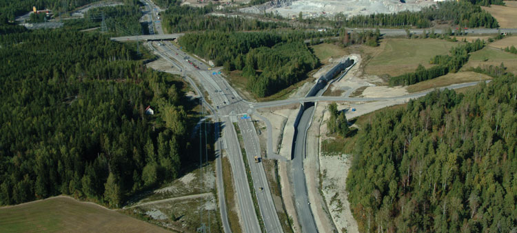

Figure 1: Location of the Vuosaari Harbour and main cargo routes
A new harbour is presently being built in Finland’s capital and will be ready by the end of 2008. The harbour is located in Vuosaari, approximately 15km from the centre of Helsinki (see Figure 1). The Vuosaari Harbour project includes the construction of a cargo harbour as well as traffic channels – a new fairway, harbour road and harbour railway line. The harbour railway line will be 19km long and have two tunnels. With a length of 13.5km, the Savio tunnel will be the longest railway tunnel in Finland and the second longest in the Nordic countries.
The Vuosaari Harbour
The Vuosaari Harbour is being built on the site of an old shipyard. The harbour will cover 150 hectares, including 90 hectares that required filling. A business park covering 75 hectares is also being built next to the harbour. The harbour will have 3.6km of quays and 20 berths. It will only handle unitised cargo packed in containers, trucks and trailers. The harbour will provide jobs for approximately 4,000 people and will have good public transport links.
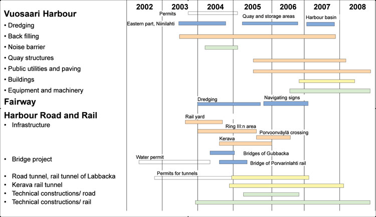
Figure 2: Project timetable
The harbour project, in which environmental matters have been carefully taken into consideration in planning and implementation, got under way at the end of 2002. By the end of 2008, the harbour will be completed to the extent that cargo traffic can be moved to Vuosaari from Helsinki’s existing harbours. Traffic channels will be ready at this time, along with a large part of the business park. The harbour will reach its full extent by the end of 2009.
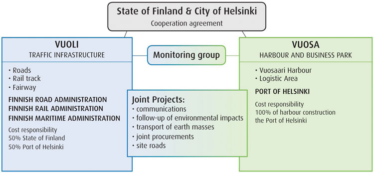
Figure 3: Organisation of the harbour project
The Vuosaari Harbour has been planned so that it will have a maximum throughput of 12,000,000 tonnes a year. Of this total, approximately 2,400,000 tonnes (20%) will be transported by rail. According to projections, this will be broken down into 1,800,000 tonnes arriving at the harbour and 600,000 tonnes leaving the harbour by rail.
Organisation and costs
The harbour project has been divided according to implementing organisations and financing arrangements as follows:
- The Port of Helsinki’s VUOSA project is responsible for developing and building the harbour and the logistics area next to it. The Port of Helsinki will pay for building the harbour
- The VUOLI project, which includes the Finnish Road Administration, the Finnish Rail Administration and the Finnish Maritime Administration, is in charge of planning and building traffic channels (harbour road, harbour railway line and fairway). The VUOLI project will pay 50% of the costs of traffic channels and the Port of Helsinki 50%
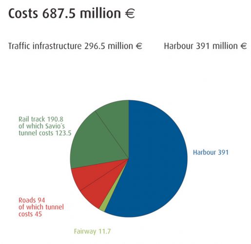
Figure 4: Costs of the Vuosaari harbour project
This is the first time the Finnish Road Administration, the Finnish Rail Administration and the Finnish Maritime Administration have worked together to such an extensive degree in the same project. The VUOSA and VUOLI projects have been carefully coordinated. Joint functions include the handling of soil and rock, communications, site traffic arrangements and the monitoring of environmental impacts.
The harbour project will have a total cost of approximately €680 million, broken down as shown in Figure 4.
Traffic connections
In planning the harbour project, environmental considerations have played a key role and new traffic channels have been located in tunnels or in existing corridors for the most part. New road and railway connections will link the harbour to major roads and the main railway line (see Figure 5).
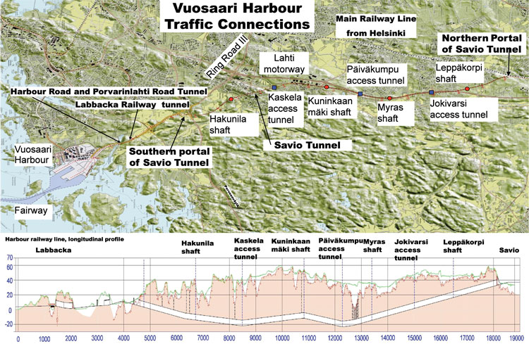
Figure 5: Map and profile of traffic connections, also showing shatts and access tunnels for the Savio railway tunnel
The fairway leading to the harbour, with a draught of 11 metres and a length of 36km, was planned so as to be as safe and easily navigable as possible. Dredging was required over a distance of 2km, and dredged soil and rock was mostly used to fill in the harbour area.
The new harbour road (Satamatie) leading to Ring Road III goes under Porvarinlahti Bay and the Labbacka Natura 2000 area in a 1.6km tunnel with double lanes in separate tubes that are well illuminated. The road was opened to traffic in December 2007.
The new 19km railway line will improve rail connections for cargo traffic. It will provide a fast and safe link to the main line between Helsinki and Tampere and inland terminals along the way. The railway line will be completed and go into service in November 2008.
Construction on the environment’s terms
The harbour and new traffic channels run through areas that have considerable importance for nature conservation and recreation, and extensive environmental impact assessments were conducted in planning the project and as part of the permit and notification procedure. In planning and approving the Vuosaari Harbour and traffic channels for it, attention has constantly been paid to environmental impacts as well as financial and technical matters, and this has essentially influenced planning solutions.
In building the harbour road and railway line, the moving of soil and rock has been coordinated with the construction of the harbour, fairway and logistics area to provide the optimal solution in terms of overall economy. The harbour road and railway line follow the same corridor between tunnels and their construction has been carried out together. This also saved space and made it easier to plan noise abatement and landscaping. Construction of the Porvarinlahti railway bridge and the portal of the Labbacka tunnel took place outside the breeding season for birds.
The construction of harbour traffic channels produced approximately 300,000 cubic metres of soil and approximately 1,900,000 cubic metres of rock. This has been used as fill in the harbour area and in structural layers, noise barriers and landscaping for traffic channels.
Harbour railway line
The harbour railway line will be 19km long and have a single track that is electrified (1*25 kV), blocked and equipped with automatic train protection. The line will only be used for freight traffic, with a maximum axle load of 25 tonnes. It will initially handle 10 trains a day, five in each direction. This is expected to increase to a maximum of 16-20 trains a day. The line will have a maximum speed of 80km/h. Thanks to the long railway tunnel, rail traffic will not disturb residents. The line will have no level crossings. The track will consist of 60E1 rails on concrete sleepers and ballast. Trains can have a maximum length of 725 metres and a maximum weight of 4,500 tonnes.
When the harbour goes into operation, the volume of traffic will be 5-6 trains a day in each direction plus 3-4 additional trains a week and even more at peak periods. As a rule, trains will generally arrive during the night and morning and depart during the evening.
The harbour railway line will split off from the main line in the Savio section of Kerava, approximately 25km from Helsinki. Here it will enter the 13.5km Savio railway tunnel and run as much as 60 metres below the surface in some places before resurfacing next to Ring Road III.
After the Savio tunnel, the line will follow the same corridor as Ring Road III and the harbour road for approximately 2km and then run under the Labbacka Natura 2000 area in a second tunnel appromximately 0.7km long. Then it will cross the Porvarinlahti railway bridge, in designing which special emphasis has been placed on noise abatement and water protection, and enter the yard, which will have eight tracks where shunting operations can occur.
Only electric locomotives and rolling stock approved for rail traffic in Finland will be used on the line. Tank wagons will not be allowed; instead hazardous substances will be transported in tank containers or unit good containers. Diesel locomotives, which will take care of shunting work in the yard, will occasionally travel through the tunnel between the harbour and the main line. Diesel equipment will also be used in line maintenance work.
Traffic on the line will be remote controlled from the traffic management centre for southern Finland. The traffic control and safety equipment system together with automatic train protection will prevent the possibility of a collision between trains going in opposite directions or of a rear-end collision. Communication between traffic control and trains will take place over the GSM-R network.
Savio railway tunnel
The Savio railway tunnel will be 13.5km long with a single track and have short concrete portal structures at both ends. Figure 8 on page 35 shows a cross-section of the tunnel. The tunnel will have a maximum gradient of 1:100 and a minimum curvature radius of 1,000 metres. The lowest point in the tunnel will be 23 metres below sea level and the tunnel will run as much as 60 metres below the surface. The southern portal of the tunnel is five metres above sea level and the northern portal 33 metres above sea level. There are four access tunnels and four shafts leading to the tunnel. The access tunnels will serve as maintenance routes and in an emergency as exits, rescue routes and air shafts. The shafts will serve as exits, exhaust shafts and rescue routes. Access tunnels and shafts will be separated from the railway tunnel with sectioning walls and doors.
During the planning stage extensive soil, rock and groundwater investigations were conducted in order to determine the best places for tunnelling. Nearby, areas were also surveyed to determine the types of foundation used in buildings and places where there was a chance that settling might damage municipal engineering. On the basis of investigations, risk areas were mapped and strict requirements were set for permissible leakage (min. 2 l/min/100 m) into the tunnel. During construction the rock mass around the tunnel was grouted in risk areas to prevent negative impacts on groundwater or vegetation located overhead.
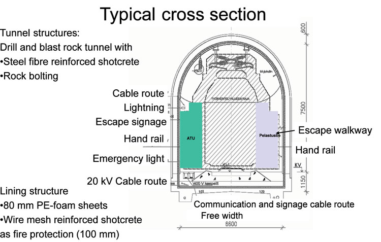
Figure 8: Basic cross section of the Savio tunnel
The environmental impacts of tunnel construction were closely monitored. During excavation work regular surveys, noise and vibration measurements and groundwater measurements were conducted in nearby areas. All measurement information was collected in a single database. For monitoring purposes an online service was created and through this all the results of measurements could be checked practically in real time.
The construction of the Savio tunnel was carried out by a number of contractors. Excavation was divided into five contracts so that work could be done according to the fairly tight timetable. Excavation contracts included the excavation and reinforcement of the tunnel as well as shafts and access tunnels and facilities for technical systems. Excavation work began in September 2003 and was completed in autumn 2006. Subsequently separate contracts have covered the installation of structures and technical systems, superstructure, electrified line technology and CCS-equipment.
Tunnel structures
The tunnel was built entirely using the drill and blast method. The quality of the bedrock was mostly fair to good, although a few weak fracture zones were encountered along the way. The tunnel was sealed by cement grouting, galvanised bolts and shotcrete were used in reinforcement.
In the Myras area, the bedrock was of very poor quality and there were numerous thick clay zones. For this reason excavation over a distance of approximately 300 metres was carried out in stages and the roof of the tunnel was shored up with preinstalled bolts. The bedrock in this area was so weak that the tunnel could not be built using traditional reinforcing methods and still meet requirements for the service life of load-bearing structures. Consequently, a concrete tunnel with a structural thickness of 800mm was built over a distance of 230 metres (see Figure 9). The structure is under pressure from the layers of soil overhead and approximately 50m water pressure.
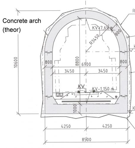
Figure 9: Cross-section of the concrete tunnel section of the Savio tunnel
Since the difference in elevation between the portals of the tunnel was large, gravitational ventilation results in a chimney effect, with air naturally flowing from the lower portal towards the upper end of the tunnel. In winter this causes cold air to reach deep in the tunnel and particularly near the portals this can lead to the formation of ice on the roof and walls of the tunnel. To prevent the formation of ice, the decision was made to install heat and water insulation structures at both ends of the tunnel. The selected insulation solution was ÖS-Lining, with polythene sheets being attached to the walls of the tunnel and fire protected with a 100mm layer of wire mesh reinforced shotcrete. Lining structure was installed over a distance of 300 metres at the northern portal and 600 metres at the southern portal.
The southern portal of the tunnel is equipped with an automatic door that keeps gravitational air flow and cold from reaching far into the tunnel. The door is normally closed, but when a train approaches the tunnel from the south or the southern portal of the tunnel from the north, it opens automatically. The door is connected to the line’s CCS-system and whether the door is open can be checked before a train approaches the portal. The door is equipped with primary and pre-signals.
Tunnel structures have been dimensioned for the air pressure variations caused by rail traffic and for the fire and explosion pressure loads in accident situations. The pressure load on structures will vary between ± 5 KPa. The large pressure variation is due to the fact that when a train enters the northern portal of the tunnel, the door at the southern portal will still be closed. Thus the pressure shock caused by a train cannot be immediately released but will form a sizeable load impulse on the tunnel’s structures and equipment.
Since the tunnel goes under residential areas, the possibility of disturbance travelling through rock and soil has also been studied. The source of disturbance is vibration due to friction between train wheels and rails, which is carried by track substructures to the bedrock. In bedrock vibration is rapidly dampened but it can be a problem in neighbouring areas, particularly at higher frequencies where it is audible. The result is referred to as structure-borne noise, which in some circumstances can be heard at a distance of over 100 metres from the tunnel if a building has its foundation on bedrock. Sub-ballast mats have been installed in the Savio tunnel over a distance of approximately 8km, so the risk of disturbance due to structure-borne noise has been minimised.
Safety and operating systems in the tunnel
The Savio railway tunnel can be entered through four access tunnels and four vertical shafts. The access tunnels will serve as maintenance routes and in an emergency as exits, rescue routes and air shafts. The shafts will serve as exits, exhaust shafts and rescue routes. Access tunnels and shafts will be separated from the railway tunnel with sectioning walls and doors.
Tunnel safety will be ensured with precautionary measures and an efficient fire extinguishing system. The risk of an accident is small since only one train will be in the tunnel at a time. The tunnel will be monitored with cameras and have communication links. The safety and operating systems have been designed to ensure the safety and working conditions of train crews as well as maintenance and rescue personnel. In an emergency, maintenance routes and vertical shafts at intervals of 1.5-2 kilometres can be used as exits.
A hot-box detector will be installed on the line between Helsinki and Tampere so that a freight train with a defective axle or brake can be stopped before it enters the tunnel. This arrangement complies with SRT TSI recommendations aimed at reducing risks in railway tunnels. There will not be a hot-box detector between the harbour and the tunnel, since trains will be inspected in the yard before departure.
Tunnel structures and technical systems are based on a risk analysis that was conducted during the planning stage. On the basis of the analysis, there are no significant risk points in the tunnel, but in designing systems, attention has been paid to the possibility of a fire and problems that might be encountered in extinguishing a fire or removing smoke.
Clean water will be piped from drains to pumping plants located at access tunnels and will then be pumped to drainage ditches near the portal of each access tunnel. Pumping plants will have separate collection and back-up pools for water coming from different directions. The pools have been dimensioned so that they can handle water flowing in an emergency situation. The pumping plants will be equipped with oil separation systems and hazardous substance detectors, and back-up pools can be emptied into a tank truck at the lower level of an access tunnel in an emergency.
The railway tunnel will be illuminated around vertical shafts and access tunnels and at both ends with fluorescent lights over a distance of 200-400 metres. In some places for example, there will be supplementary lighting for video cameras. Normally, lighting will only be used near the portals of the tunnel or in accident or maintenance situations. Signage and safety lighting that meets SRT TSI requirements will lead to exits in accident situations.
The electrical feed for the tunnel’s operating system has been connected to the 20 kV network from two directions, so a defect in one direction will not cause a long outage. The 20 kV wire has been installed into the track substructure and fire protected. Transformers and main distribution boards have been located in connection with access tunnels and vertical shafts and at turning points in the longest tunnel segments. Power current distribution boards for maintenance and rescue activities have been located at the portals and at intervals of approximately 100 metres in the tunnel.
The tunnel has been equipped with a leaking antenna cable system that allows links between the official GSM network (VIRVE) and the GSM-R network. Emergency phones will be located at turning points and at intervals of 350 metres in the tunnel and in technical facilities. Picking up a phone will automatically connect it to the tunnel control centre, which will be able to locate the phone from which a connection originates. If an emergency phone is disconnected from the cable network, this will send an alarm to the control centre. The tunnel will have a field phone network for the rescue department.
Ventilation will take place via the portals of the tunnel when a train pushes a column of air before it. Smoke exhaust fans have been located at the portals of the tunnel and at vertical shafts. Smoke exhaust systems have been dimensioned assuming that the air flow is 2 m/s and that air changes at least three times an hour in a tunnel segment. To ensure smoke exhaust, the tunnel will have smoke curtains that will allow the tunnel to be sectioned. Smoke curtains will be closed manually and locked to the track structure. Ventilation during repair and maintenance work will be carried out with smoke exhaust fans or auxiliary fans.
The tunnel will have an emergency earthing system to protect rescue and maintenance activities. The system will ensure that electricity is turned off if rescue department personnel have to enter the tunnel during an emergency. Grounding separators will be located in connecting structures and the operating panel will be on the side of the connecting structure. The panel will have a display that shows whether electricity has been turned off.
The Savio railway tunnel will be equipped with a fire hydrant network and the fire water network will be a dry network. Fire water stations will be located at the portals of the tunnel and at the top of vertical shafts for pressurising and filling the network. Fire hydrants will be located in the tunnel at intervals of approximately 100 metres. Portable fire extinguishers will be installed at pumping plants, vertical shafts and distribution boards. An optical-cable fire alarm system will be installed in the tunnel.Technical facilities will be equipped with heat and smoke detectors. Emergency phones and fire alarm buttons will be installed at intervals of 300-400 metres at turning points for rescue vehicles and in technical facilities. The tunnel will also have a crime report system. The railway tunnel, access tunnels, vertical shafts and main entrances to access routes will be equipped with motion detectors. The status of the system and alarms will be displayed in the control room. The system will automatically control video cameras and recording functions. The portals of the tunnel and the entrances to access tunnels and vertical shafts will be equipped with recording video cameras. The doors leading to access tunnels and vertical shafts will be equipped with access control automation so that rescue personnel will know which door has been used when leaving from the tunnel, for example.
For the control and monitoring of the tunnel’s operating systems and alarms, the tunnel will have a property control system. All the information in the system will be directed to the technical control room and if necessary to the traffic management centre’s control system. A heating, plumbing and ventilation monitoring system will be installed to control operating systems and for smoke removal, monitoring and alarms. All systems will have data links to the technical system control point located in connection with the operating centre for the electrified line and if necessary according to a separate plan to the company in charge of property maintenance and the rail traffic management centre.
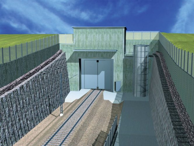
Figure 10: Conceptual view of the door at the southern portal of the tunnel